


Honeywell
MK VI MK VIII EGPWS Installation Design Guide
Proprietary notice on title page applies
CAGE CODE: 97896 SCALE: NONE SIZE: A DWG NO: 060-4314-150 REV:
SHEET
40
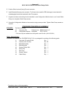
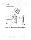
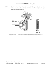
2.3.6 GPS Anten na location
The GPS antenna should be mounted on top of the fuselage in the centerline of the aircraft. Avoid mounting the
antenna near any projections, the propeller, and the T-tail of the aircraft, where shadows could occur. It is
recommended that there be a separation of at least 3 feet between the GPS antenna and any VHF Comm
antenna on the aircraft. The GPS antenna baseplate must be level within ± 5° in both axis when the aircraft is
level (level is defined as the aircraft attitude required when weighing the aircraft for weight and balance). If the
GPS antenna is tilted more than 5° or is mounted close to other objects that shadow it, loss of some of the
satellites will occur and system performance degraded. See manufacturer for specifications of GPS antennas.
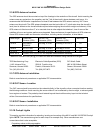
Some GPS Antenna cable and connector information, including vendor information, is listed below.
Cable Length Cable Part
Number (VPN)
EGPWS TNC
Connector (VPN)
Antenna TNC
Connector (VPN)
Max Loss*
0 to 40 ft RG142B/U
RG400/U
TED Mfg. 5-10-30 TED Mfg. 5-30-102-1 8.0
0 to 80 ft ECS 311601 TED Mfg. 5-10-307 TED Mfg. 5-10-307 8.0
0 to 100 ft ECS 311201 TED Mfg. 5-10-306 TED Mfg. 5-10-306 8.0
100 to 165 ft Contact TED, ECS or PIC for complete cable/connector assembly
* Maximum Allowable Loss (dB) @ 1575 MHz for cable and connector using nominal 26.5 dB gain.
TED Manufacturing Corp.
11415 Johnson Drive
Shawnee, Kansas 66203
Tel: (913) 631-6211
Electronic Cable Specialists (ECS)
5300 W. Franklin drive
Franklin, Wisconsin 53132
Tel: (800) 327-9473
PIC Wire & Cable
N63 W 22619 Main Street
Sussex, Wisconsin 53089
Tel: (800) 742-3191
2.3.7 GPS Anten na Installation
Refer to manufacturer’s procedures or applicable STC documentation.
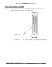
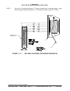
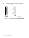
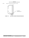
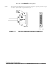
2.3.8 OAT Senso r Location
The OAT sensor should be mounted on the underside (belly) of the aircraft or other convenient location meeting
the following conditions. Avoid mounting the sensor where it can be affected by direct sunlight, or exhaust gases
from engines or heaters. The probe tip should extend beyond the aircraft boundary layer into the turbulent
airflow. See manufacturer for specifications.
2.3.9 OAT Senso r Installation
Refer to manufacturer’s procedures or applicable STC documentation.
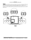
2.3.10 Cockpit Lig hts
This section provides information for selecting, locating and mounting of the MK VI and MK VIII EGPWS Cockpit
lights. NOTE: The nomenclature given for each lamp is an example only. Other manufacturers use
nomenclature that is also acceptable.