Honeywell
MK VI MK VIII EGPWS Installation Design Guide
Proprietary notice on title page applies
CAGE CODE: 97896 SCALE: NONE SIZE: A DWG NO: 060-4314-150 REV:
SHEET 297
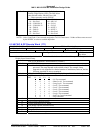
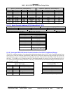
6.6 Discrete Inputs
This section contains a brief description of each input discrete is used in the EGPWS.
There are 28 possible discrete inputs each have one of the following input characteristics
1) 15 Open/Ground two state discretes
2) 13 Open/28VDC two state discretes
The EGPWS supports the following inputs in discrete form. The Level 6 audio information specifies the voice issued when
a state change occurs on the input discrete during level 6 self test. Refer to the Product Specification for self test
description.
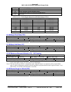
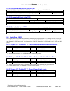
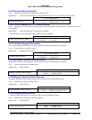
6.6.1 Analog Radio Altitude Validity Flags
A Radio Altitude Validity Flag is used by the EGPWS for analog Radio Altimeter inputs.
Type: Validity from ARINC 552, ALT 55 Radio Altimeter or RT-200/300 (analog).
Signal Status: Valid or Invalid
Level 6 Audio readout
Radio Altitude Validity Discrete #1
Valid =>
Invalid =>
“Radio Altimeter 1 Valid”
“Radio Altimeter 1 Invalid”
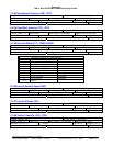
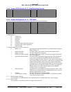
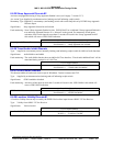
6.6.2 GND Landing Gear Discrete
Type: Supplied by landing gear or landing gear selector handle position-sensitive switch. This input can be paralleled
with, or used exclusively by a Gear Override Switch if an alternate source of Gear Position is used.
Signal Status: Landing Gear Down or Landing Gear Up
Fault monitoring: Indication of landing gear selected for more than 60 seconds at airspeeds above 290 (200 for GA Slow)
knots will result in a gear switch fault which will cause a GPW INOP indication.
Note: This can be caused by either a gear switch fault or by the Gear Override switch being left in the on position.
Level 6 Audio readout
Landing Gear Discrete
or Gear Override
Landing Gear Down =>
Landing Gear Up =>
“Landing Gear Down”
“Landing Gear Up”
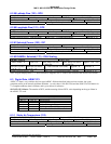
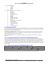
6.6.3 +28V Landing Gear Discrete
Type: Supplied by landing gear or landing gear selector handle position-sensitive switch. This input can be paralleled
with, or used exclusively by a Gear Override Switch if an alternate source of Gear Position is used.
Signal Status: Landing Gear Down or Landing Gear Up
Fault monitoring: Indication of landing gear selected for more than 60 seconds at airspeeds above 290 (200 for GA Slow)
knots will result in a gear switch fault which will cause a GPW INOP indication.
Note: This can be caused by either a gear switch fault or by the Gear Override switch being left in the on position.
Level 6 Audio readout
+28 V Landing Gear Discrete Landing Gear Down =>
Landing Gear Up =>
“28 Volts Landing Gear Down”
“28 Volts Landing Gear Up”


