Honeywell
MK VI MK VIII EGPWS Installation Design Guide
Proprietary notice on title page applies
CAGE CODE: 97896 SCALE: NONE SIZE: A DWG NO: 060-4314-150 REV:
SHEET 295
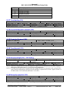
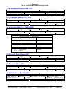
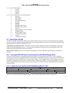
(*****) NAV Mode (binary)
0 en route
1terminal
2 approach
3 oceanic
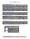
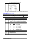
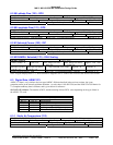
(******) Error Status (true if set; false otherwise)
0 not used
1 ROM failure
2 RAM failure
3 Nonvolatile RAM lost
4 RF failure
5 not used
6 not used
7 BaseBand ASIC failure
8 BaseBand ASIC timeout
9 not used
10 RS-232 channel 1 receiver timeout
11 EEPROM failure
12 RS-232 channel 2 fail
13 1 millisecond underflow
14 not used
15 1 millisecond overflow
6.5 Digital Data, RS-422
The MK VI and MK VIII EGPWC supports up to 3 RS-422 digital receivers (with 2 receivers having transmit capability
also) used to monitor broadcast data from other LRUs and to support interactive protocols. Each receiver channel follows
the characteristics of reference document EIA 422.
Transmission System Interconnect. Each RS-422 receiver shall be connected to an RS-422 transmitter by means of a
single twisted and shielded pair of wires. The shield shall be grounded at both ends and at all production breaks in the
cable to an aircraft ground close to the rack connector.
Receiver Bus Frequency. Receivers are capable of operating up to 38.4K baud and are determined by configuration
selection.
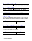
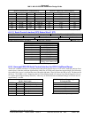
6.5.1 Honeywell RS-422 Serial Control Interface (SCI) Mode/Range Word
The Serial Control Interface is transmitted on an RS-422 data bus. The data stream consists of 13 words (a label byte
followed by two data bytes) transmitted within 47 milliseconds. Each character consists of one bit (Low), 8 data bits with
least significant bit first; an ODD parity bit and one stop bit (high). The most significant bit of the character is a label or
data flag bit. The data rate of the SCI bus is 12 KBS ±0.01%. Channel 429_422RX_1 (J2-36/37) and 422RX_2 (J2-10/11)
can be configured for this input. Only two of the words on the bus are decoded, Label 80 Mode/Range Word 1 and Label
FF Status Word 1.
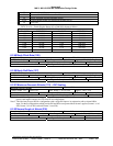
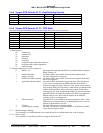
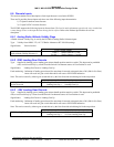
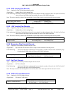
6.5.1.1 Serial Control Interface (SCI) Mode/Range Word 1 (80)
Mode/Range Word 1
Source: Map Electronics Unit (MEU)
LABEL (Hex) 80 Units: N/A Max. Range: N/A Approx. LSB: N/A
Data Bit: 1 – 8 + = N/A Sign Bit: N/A Pad Bits: N/A
Transmit Interval (mSec): See above Data Type: Discrete SDI Bits: N/A
Note this is an RS-422 serial data stream not ARINC 429 so SDI and SSM for this word are not applicable.


