


Honeywell
MK VI MK VIII EGPWS Installation Design Guide
Proprietary notice on title page applies
CAGE CODE: 97896 SCALE: NONE SIZE: A DWG NO: 060-4314-150 REV:
SHEET
118
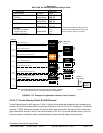
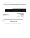
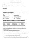
4.4.2 EGPWC Fro nt Panel Test Connector
The RS-232 interface with the EGPWC is accomplished via a test connector provided on the EGPWC front
panel (J3). This provides access for a PC test monitor and portable data loading capabilities. The mating
connector for the EGPWC test plug (P3) is a male, 15 pin, double density D-subminiature type (or equivalent).
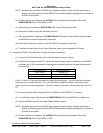
The connection between the PC serial port connector (with standard DB9) and the EGPWC RS-232 interface is
defined as follows:
RS-232 Receive RS-232 Transmit RS-232 Ground
EGPWS Front Connector (J3)
Pin 3 Pin 4 Pin 1
Standard (PC)* DB9 Connector
Pin 2 Pin 3 Pin 5
*NOTE: Some PC Comm Ports have Pins 2 & 3 reversed from what is described above.
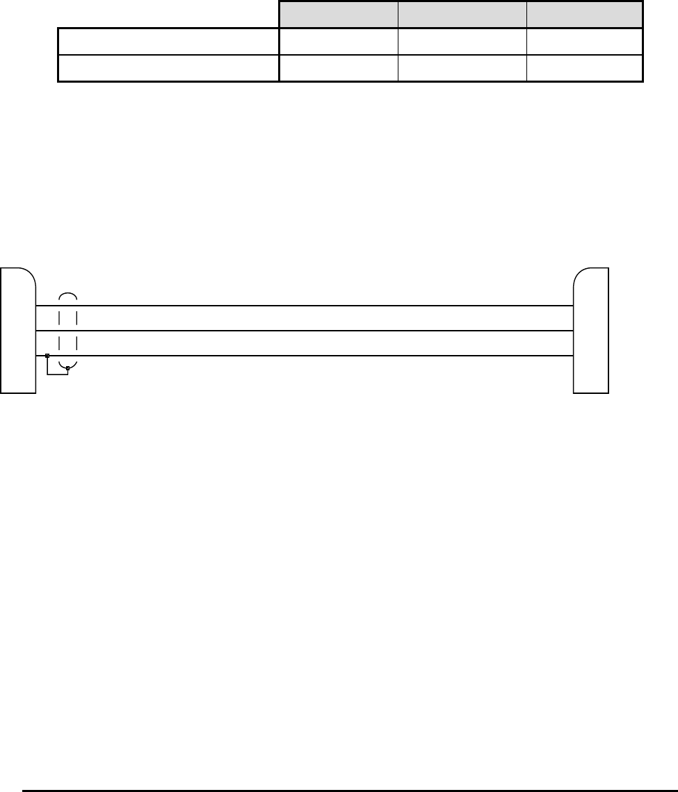
Connector, AMP 205161-1
Socket Contact, AMP 205090-1, QTY 3
M39029/63-368
P
COM
Connector, AMP 204513-2*
Pin Contact, 204370-2, QTY 4*
M39029/58-360
Backshell, AMP 745854-5
Jackscrew, AMP 747784-3
Grommet Set, AMP 747746-1
P3
2
3
5
3
4
1
Length as required (5' to 50')
* Alternate part number 748364-1 connector and 748333-4 or -7 pin contact.