


Honeywell
MK VI MK VIII EGPWS Installation Design Guide
Proprietary notice on title page applies
CAGE CODE: 97896 SCALE: NONE SIZE: A DWG NO: 060-4314-150 REV:
SHEET 252
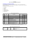
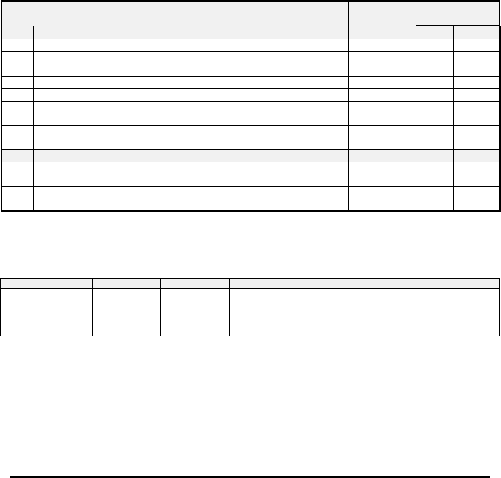
5.3.10 Category 10, Attitude Input Select
The following table provides identification of the Attitude Roll Angle type. The entry in the Attitude Input Select
corresponds to a table that provides detailed information on the configuration. For example, the details for Attitude Input
Select #2 are found in 5.3.10-2.
In this category, only the following signals are defined:
• Roll Attitude.
• Pitch Attitude
• Roll Rate
• Pitch Rate
• Normal Acceleration
• Longitudinal Acceleration
• Inertial Vertical Speed
• Inertial Altitude
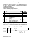
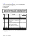
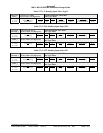
Table 5.3.10: Attitude Input Select
ID
Attitude Input
Select
Description
Software
Effectivity
EGPWS
Effectivity
(Table 5.3.10-x)
MKVI MKVIII
0 0 Analog Roll without validity (3-Wire Synchro) -020 X X
1
2 2 Analog Pitch and Roll (3-Wire Synchro) -020 X X
3
4 4 Analog Roll with validity (3-Wire Synchro) -020 X X
55
Digital Pitch and Roll
(ARINC 429 High Speed) (Note 2)
-020 X X
66
Digital Pitch, Roll, and Vertical Speed
(ARINC 429 High Speed) (Note 2)
-020 X X
253 253
Digital Pitch, Roll, Vertical Speed and Altitude
(ARINC 429 via dual IOC buses) (Note 1)
-020 N/A X
255 255
Digital Roll and Acceleration
(ARINC 429 via dual IOC buses) (Note 1)
-020 N/A X
Note 1: ID 253 and 255 may only be used in conjunction with other IOC bus selections for categories 2,6,8,9,11 and 12.
Note 2: Category 10 and Category 11 use the same ARINC 429 receiver if a digital source is selected.
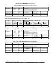
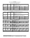
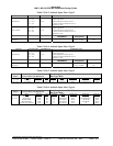
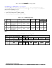
Table 5.3.10-0: Attitude Input Select Type 0
SIGNAL CONNECTION REFERENCE SUMMARY DATA
Roll Attitude
(X) = J1-1
(Y) = J1-21
(Z) = J1-2
6.1.8
Format: 3 Wire Synchro
Input Type: Basic
Fault Designation: ROLL FAULT
Validity: None
Reference: None