


Honeywell
MK VI MK VIII EGPWS Installation Design Guide
Proprietary notice on title page applies
CAGE CODE: 97896 SCALE: NONE SIZE: A DWG NO: 060-4314-150 REV:
SHEET
84
HONEYWELL
MK VI-VIII
EGPWS
965-1XXX-0XX
J2
ARINC 453 OUTPUT (A)
ARINC 453 OUTPUT (B)
58
59
P P
RANGE INPUT (A)
RANGE INPUT (B)
37
36
P
P
P1
3*
4*
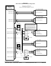
#1 - IOC (ICC-4000)
PROLINE 4 INTERFACE
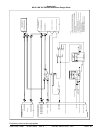
MK VI-VIII EGPWS Category 6, ID 5 or 6
P1
8D
10D
#1 - MFD
H - ARINC 453
L - (70 ohm terminated)
4
29
#1 - WXR
H
L
P
P1
P P
RANGE INPUT (A)
RANGE INPUT (B)
41
40
P1
3*
4*
#2 - IOC (ICC-4000)
ARINC 453 OUTPUT (A)
ARINC 453 OUTPUT (B)
56
57
P
P
P1
8D
10D
#2 - MFD
H - ARINC 453
J1
LA-GP-5 bus (Label 271)
RA-GP-5 bus (Label 271)
* ICC-851A pins 13 & 14
* ICC-851A pins 13 & 14
11D L - (unterminated)
11D L - (unterminated)
L - (70 ohm terminated)
TERR RLY SELECT #1 54
TERR
+28 VDC
MOM TERR SELECT #1 32
TERR
+28 VDC
TERR RLY SELECT #2 49
MOM TERR SELECT #2 31
ARINC 453 OUT
+28 VDC
+28 VDC
70
!
*
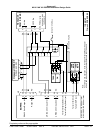
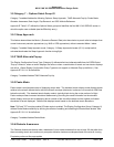
* In the OEM installations a single weather radar 453
bus enters the left MFD, passes through, and is
terminated (70 ohm) at the right MFD. For EGPWS
installations break the 453 radar bus between the
MFDs, install switching relays, and wire one relay to
each MFD. The right MFD connection is moved to
remove the 70 ohm termination at that MFD. To allow
proper radar termination when EGPWS is passing
through the relays, the radar picture bus has a 70 ohm
resistor (added externally).