


Honeywell
MK VI MK VIII EGPWS Installation Design Guide
Proprietary notice on title page applies
CAGE CODE: 97896 SCALE: NONE SIZE: A DWG NO: 060-4314-150 REV:
SHEET
58
62
43
9
25
63
44
53
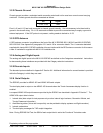
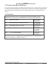
J1
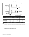
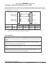
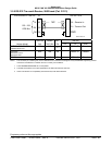
Altitude Out
Signal Common
BIT Out
Analog Air Data ComputerEGPWS MK VI / MK VIII
(+)
(-)
Uncorrected
Barometric
Altitude
Baro Altitude Valid +28V
(+)
(-)
Temp. Input
Chassis Ground
+5V Excitation
500 ohm
Temperature
Probe
Analog-ADC.vsd
Cat 2 Uncorrected Baro Altitude
1
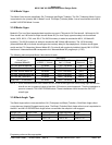
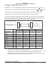
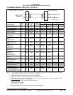
Vendor Model ID Altitude Out Common BIT Out
CIC 04077 0 J1-F J1-G J1-E
Collins ADS-65 3 J1-12 J1-13 J1-5
CIC 02702 4 J1-A J1-B J1-E
Honeywell AZ-241 11/12
2
J1A-63 J1A-11 (CGND) J1A-12
Honeywell AZ-242
4
11/12
2
J1B-17
4
J1A-11 (CGND) J1A-12
Honeywell AZ-648 11/12
2
J1-J J1-G J1-U
Honeywell AZ-800
3
11/12
2
J1A-78 J1A-10 (CGND) J1A-34
Honeywell AZ-810
3
11/12
2
J1A-78 J1A-10 (CGND) J1A-34
Honeywell AZ-252 11/12
2
J1A-17 J1A-10 (CGND) J1A-34
NOTES:
1 The connector pin numbers given in the Table above are to the best knowledge of Honeywell EGPWS engineering. Please
contact the manufacturer’s customer service to confirm your installation.
2 ID 12 does not require an OAT input, instead a constant temperature of 25 deg C is assumed.
3 Honeywell AZ-810 should only be used as an analog source if it does not have a digital interface.
4 Honeywell AZ-242 with part numbers 4013242-708, -709, -710, -712, -713 and –742 have DC Altitude out at pin J1B-17. Part
numbers 4013242-709 and -711 have DC Altitude out at pin J1A-40.