


v
List of Figures
••••••••••••••••••••••••••••••••••••••••••••••••••
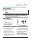
Figure 3-1: Installing the Lock...............................................................................................................................................3-1
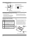
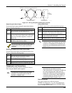
Figure 3-2: Cabinet Attack Resistance Considerations.........................................................................................................3-2
Figure 3-3: Mounting the PC Board.......................................................................................................................................3-2
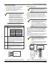
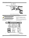
Figure 3-4: Keypad Connections to Control Panel ................................................................................................................3-3
Figure 3-5: Using A Supplementary Power Supply...............................................................................................................3-3
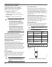
Figure 3-6: Wiring Polarized Fire Devices.............................................................................................................................3-4
Figure 3-7: Wiring Nonpolarized Burglary Devices..............................................................................................................3-5
Figure 3-8: Telephone Line Connections................................................................................................................................3-6
Figure 3-9: Wiring Connections for Zones 1-9 .......................................................................................................................3-6
Figure 3-10: 2-Wire Smoke Detector on Zone 1.....................................................................................................................3-7
Figure 3-11: 4-Wire Smoke Detectors ....................................................................................................................................3-8
Figure 3-12: Wiring a 333PRM to the Control.......................................................................................................................3-8
Figure 3-13: Wiring a 333PRM using a 4204 ........................................................................................................................3-9
Figure 3-14: Wiring a 333PRM using a 4204 and a Power Supply......................................................................................3-9
Figure 3-15: Wiring Latching Glassbreaks to Zone 8...........................................................................................................3-10
Figure 3-16: Polling Loop Connections to the VISTA-40 ....................................................................................................3-11
Figure 3-17: Polling Loop Connections Using One 4297 Extender Module .......................................................................3-12
Figure 3-18: Polling Loop Connections Using Multiple Extender Modules .......................................................................3-12
Figure 3-19: Installing the 5881ENHC with Tamper Protection ........................................................................................3-13
Figure 3-20: 5881 RF Receiver (cover removed) ..................................................................................................................3-14
Figure 3-21: 4204 Relay Module...........................................................................................................................................3-17
Figure 3-22: 4204CF Relay Module......................................................................................................................................3-17
Figure 3-23: Ground Start Module Connections..................................................................................................................3-18
Figure 3-24: Remote Keyswitch Wiring...............................................................................................................................3-19
Figure 3-25: Remote Keypad Sounder Wiring.....................................................................................................................3-19
Figure 3-26: 4100SM Using a Serial Printer........................................................................................................................3-20
Figure 3-27: VIP Module Connections .................................................................................................................................3-21
Figure 3-28: UVS Connections to the Control Panel...........................................................................................................3-23
Figure 3-29: 1361 Transformer and Battery Connections ..................................................................................................3-24
Figure 3-30: 1361X10 Transformer Connections.................................................................................................................3-24
Figure 6-1: Direct-Wire Downloading Connections...............................................................................................................6-3