


VISTA-40 Installation and Setup Guide
3-4
Installing External Sounders
The VISTA-40 provides a bell circuit output for
operating fire and burglary alarm notification
appliances. The alarm output is rated as follows:
10VDC – 14VDC, 1.7A max., power-limited.
The output has the following options:
• Selectable for supervision.
• Selectable for confirmation of arming ding.
• Selectable to chime when entry/exit or perimeter
zones are faulted.
• Selectable for no timeout or timeout of 2-30
minutes.
U
L
• Burglary bell circuits must be programmed
for a timeout of 16 minutes or longer.
• For Household Fire and combination
Household Fire/Burglary installations, the
total current drawn from the auxiliary power,
polling loop, and alarm output combined
must not exceed 750mA.
• For Household Burglary installations, the
total current drawn from the alarm output
must not exceed 1.7A. A battery must be
installed, as it supplies the current for the
combined auxiliary power, polling loop, and
alarm output in excess of 750mA.
UL1023 Household Burglary Installations
For Household Burglary installations, the total current
drawn from the alarm output must not exceed 1.7A. A
battery must be installed, as the battery supplies
current from the combined auxiliary power, polling
loop, and alarm output in excess of 750mA.
UL985 Household Fire or Combination Household
Fire/Burglary Installations
For installations that must provide UL Listed
protection, the total combined current drawn from the
alarm output, auxiliary power output, and polling loop
must not exceed 750mA in order to comply with the
battery independence requirements. If, for example,
two System Sensor PA400 piezo alarm sounders, wired
in parallel, are used (24mA total), then 726mA (750mA
– 24mA) is available for auxiliary output and polling
loop use.
Non-UL Installations
For non-UL installations, the total current drawn from
this output can be up to 1.7 amps. A battery must be
installed, as the battery supplies current in excess of
750mA. Up to two 719 sirens can be used wired in
parallel.
U
L
This control complies with National Fire
Protection Association (NFPA) requirements for
temporal pulse sounding of fire notification
appliances.
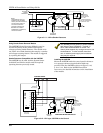
Alarm Output Supervision
When supervision is enabled, the VISTA-40 monitors
the alarm output wiring for open and short circuit
faults while the output is inactive. The system provides
a trouble indication (Zone 70) when an open occurs; or
when a short occurs between the Bell (+) and Bell (-)
terminal wiring, or between the Bell (+) terminal wiring
and earth ground.
The VISTA-40 indicates the trouble condition
regardless of whether the system is armed or disarmed.
The zone displays on the keypads, reports to the event
log, and transmits to the central station (if
programmed) on Partition 1. The Contact ID event code
is 321, Bell Trouble. The trouble is cleared from the
display by entering the user code + OFF.
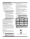
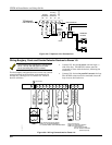
Wiring the Alarm Output
The wiring of the alarm output depends upon whether
you are going to supervise the output or not. Use the
appropriate procedure below for your application.
U
L
Use only UL Listed sounding devices for UL
installations.
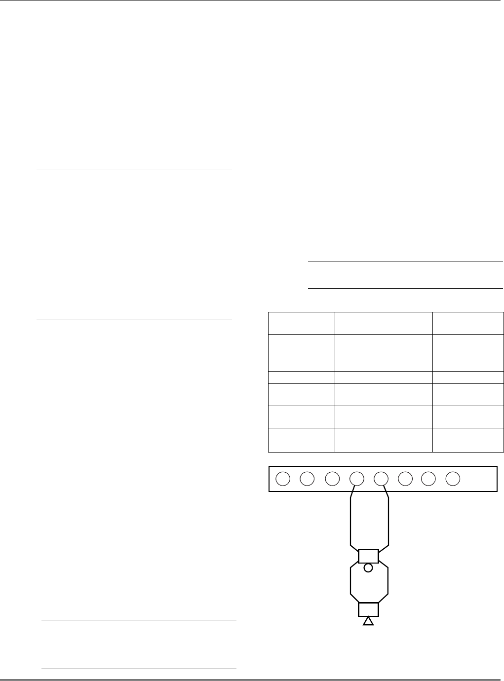
Compatible Alarm Indicating Devices
Model Number Device Type Polarizing
Diode
719 Compact Outdoor Siren
(not UL Listed)
Yes
747 Indoor Siren Yes
AB12 Grade A Bell Yes
System Sensor
MA 12/24D
Fire Piezo Horn No
System Sensor
P12575
Fire Horn/Strobe No
Wheelock
AS-121575W
Fire Horn/Strobe No
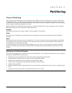
ALARM SOUNDER OUTPUT:
1-VDC - 13.8VDC
1.7A MAXIMUM
BELL
HORN
7
6
+
-
+
-
8
3
1
2
4
fire_devices-001-V0
5
Figure 3-6: Wiring Polarized Fire Devices