


VISTA-40 Installation and Setup Guide
3-18
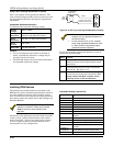
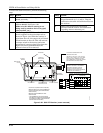
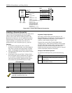
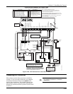
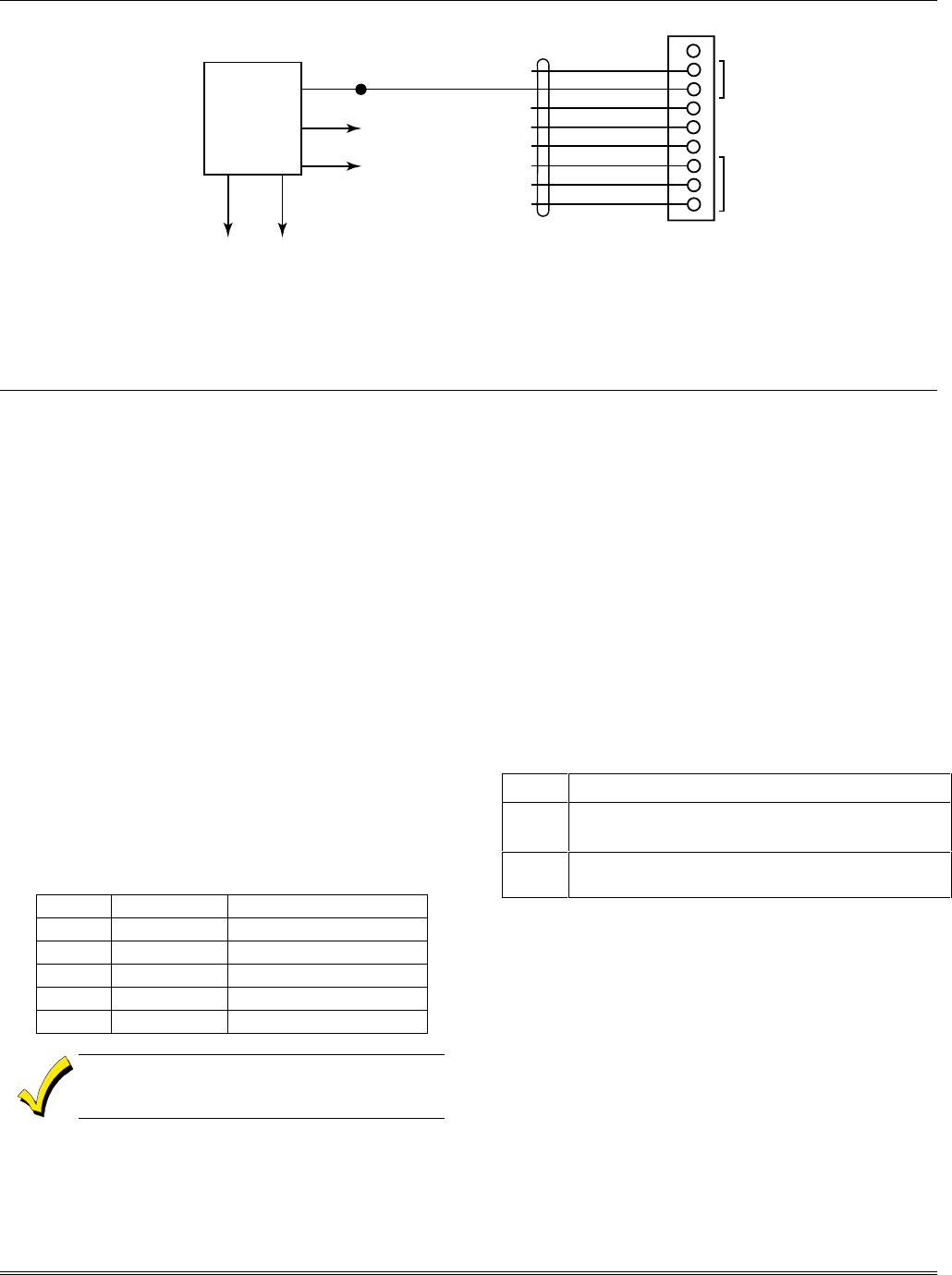
123456789
4142TR
CABLE
GRAY (GROUND)
YELLOW (OUT 1)
RED (OUT 2)
GREEN (GROUND)
BROWN (OUT 3)
BLUE (GROUND)
BLACK (OUT 4)
WHITE (GROUND)
J7 CONNECTOR
N/U
IF USED:
1. OUT 1 IS NO LONGER
USABLE FOR SMOKE DETECTOR RESET
(SEE FIELD 1*46).
2. OUT 2, 3, 4 CAN STILL BE
USED TO PROVIDE ALARM
STATUS INDICATIONS OR
TO OPERATE A KEYSWITCH
(SEE FIELD *15).
3. THE 675 IS NOT UL LISTED.
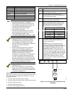
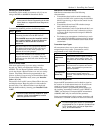
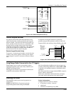
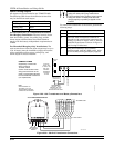
BROWN
GROUND START
TRIGGER
BLUE
GREEN
BLACK
VIOLET
TO AUX. POWER
TERM. 7
TO AUX. POWER
TERM. 6
(50mA CURRENT DRAW)
675
GROUND
START
MODULE
(CUT ORANGE
JUMPER)
TO
TELCO
RING
TO
EARTH
GROUND
Figure 3-23: Ground Start Module Connections
Installing a Remote Keyswitch
A UL-Listed remote keyswitch, such as the 4146, can be
used for remote arming/disarming of the burglary
portion of the system and for silencing alarms. The
keyswitch can operate in only one particular partition.
The keyswitch is wired across zone 7. This zone is no
longer available as a protection zone. Be sure to
program Zone 7 with a response type (e.g., type 10).
Operation
• A momentary short across zone 7 arms the
partition in the AWAY mode, and a short held for
more than 3 seconds arms the partition in STAY
mode. A subsequent short disarms the partition.
• The keyswitch LEDs indicate the partition’s status
(see table below).
• A momentary short across Zone 7 silences alarm
bell and keypad sounds, and disarms the system if
it was armed. A subsequent short across Zone 7
clears the alarm memory indication and resets 2-
wire smoke and glassbreak detectors (if used).
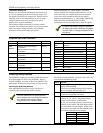
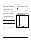
LED Indications
Green Red Indication
On Off Disarmed & Ready
Off Off Disarmed & Not Ready
Off On Steady Armed Away
Off Slow Flash Armed Stay
Off Rapid Flash Alarm Memory
The keyswitch reports as user 0, if Open/Close
reporting is enabled in field ✳40.
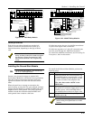
Keyswitch Tamper Operation
The tamper switch need not be used for fire or UL
Household Burglary installations. For UL Commercial
Burglary installations, the tamper switch must be
wired to a zone (zone 6 in Figure 3-24).
Program that zone for Day Trouble/Night Alarm
(response type 5). When the keyswitch is removed from
the wall, the tamper switch opens, causing an alarm or
trouble on the zone. This also causes the control to
disable keyswitch operation until the tamper is restored
and the associated partition is disarmed.
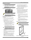
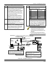
Wiring for the Remote Keyswitch
To install the 4146 keyswitch, perform the following
steps:
Step Action
1 Connect the 4146 to the panel as shown in
Figure 3-24.
2 If you are using the tamper, make sure it is
connected to a zone.