


VISTA-40 Installation and Setup Guide
3-10
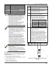
Using 2-Wire Latching Glassbreaks on Zone 8
Zone 8 can support 2-wire glassbreak detectors. The
zone provides enough standby current to power up to 50
2-wire glassbreak detectors meeting the requirements
listed below.
Compatible Glassbreak Detectors
Use detectors that meet the following ratings:
Standby
Voltage:
5VDC–13.8VDC
Standby
Resistance:
Greater than 20k ohms (equivalent
resistance of all detectors in parallel)
Alarm
Resistance:
Less than 1.1k ohms (see note below)
Alarm
Current:
2mA–10mA
Reset Time: Less than 6 seconds
NOTES:
• You can use detectors that exceed 1.1k ohms in
alarm, provided they maintain a voltage drop of
less than 3.8 volts in alarm.
• The ASC-SS1 detector has been tested and found to
be compatible with these ratings.
21
22
GLASSBREAK
DETECTOR
ZONE 8
(+)
(-)
LATCHING TYPE GLASS
BREAK DETECTOR LOOP
2000
OHMS
EOLR
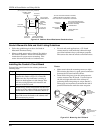
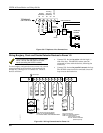
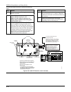
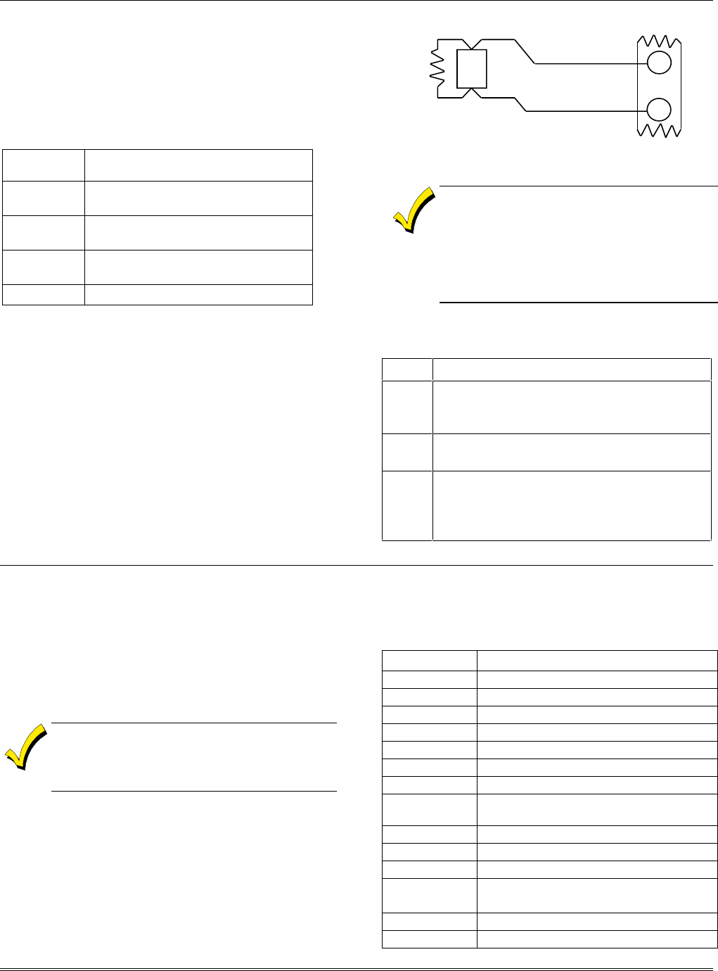
Figure 3-15: Wiring Latching Glassbreaks to Zone 8
• The alarm current provided by zone 8
supports only one glassbreak detector in
the alarmed state.
• Do not use other N.O. or N.C. contacts
when using glassbreak detectors on zone
8. Other contacts may prevent proper
glassbreak detector operation.
To wire 2-wire latching glassbreak detectors to zone 8,
perform the following steps:
Step Action
1 Select compatible 2-wire glassbreak
detectors that meet the requirements stated
previously.
2 Connect detectors across zone 8 (terminals
21 and 22). See Figure 3-15.
3 Connect the EOL resistor at the last detector
in the loop across the zone’s terminals. You
must connect the EOL resistor across
the loop wires at the last detector.
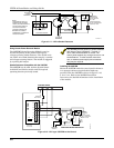
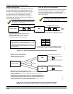
Installing RPM Devices
The polling loop provides both power and data to the
RPM devices, and is constantly monitoring the status of
all zones enabled on the loop. The maximum current
draw of all devices on the polling loop cannot total more
than 64mA (unless the system uses a 4297 Polling Loop
Extender Module).
Devices that can be programmed via either DIP
switches or the built-in unique serial number
must be set for the serial number mode
operation.
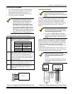
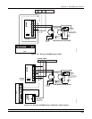
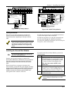
All devices on the polling loop must be wired in parallel
to the [+] and [-] polling loop terminals of the control
panel (24 and 25). You can wire from device to device,
or have multiple branches connected directly to the
control panel in a star configuration.
Compatible Polling Loop Devices
Model Number Type
4208 8-Zone Expander
4190WH 2-Zone Expander
4278 Quad PIR
4275 Dual PIR
4194 Surface-Mount Reed Contact (Wide Gap)
4297 Extender Module
4192SD Photoelectric Smoke Detector Devices
4192SDT Photoelectric Smoke Detector w/Heat
Detector
4192CP Ionization Smoke Detector
4101SN Serial Number Single-Output Relay Module
4208U Universal 8-Zone Expander
4939SN-BR
4939SN-GY
Serial Number Surface-Mount Reed
Contacts
4191SN-WH Serial Number Recessed Reed Contact
4959SN Aluminum Overhead Door Contact