


VISTA-40 Installation and Setup Guide
3-6
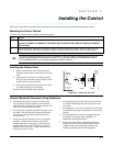
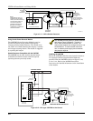
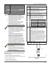
TERMINALS
ON CONTROL
EARTH GROUND
INCOMING TELCO LINE
Handset
TIP
RING
RJ31X
JACK
PLUG
DIRECT
CONNECT
CORD
TIP
RING
GROUND
PREMISES
PHONES
{
{
BROWN (TIP)
GREY (RING)
GREEN (TIP)
RED (RING)
26 27 28 29 30
Incoming
Telco Line
Figure 3-8: Telephone Line Connections
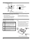
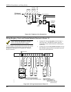
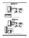
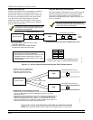
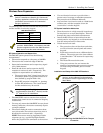
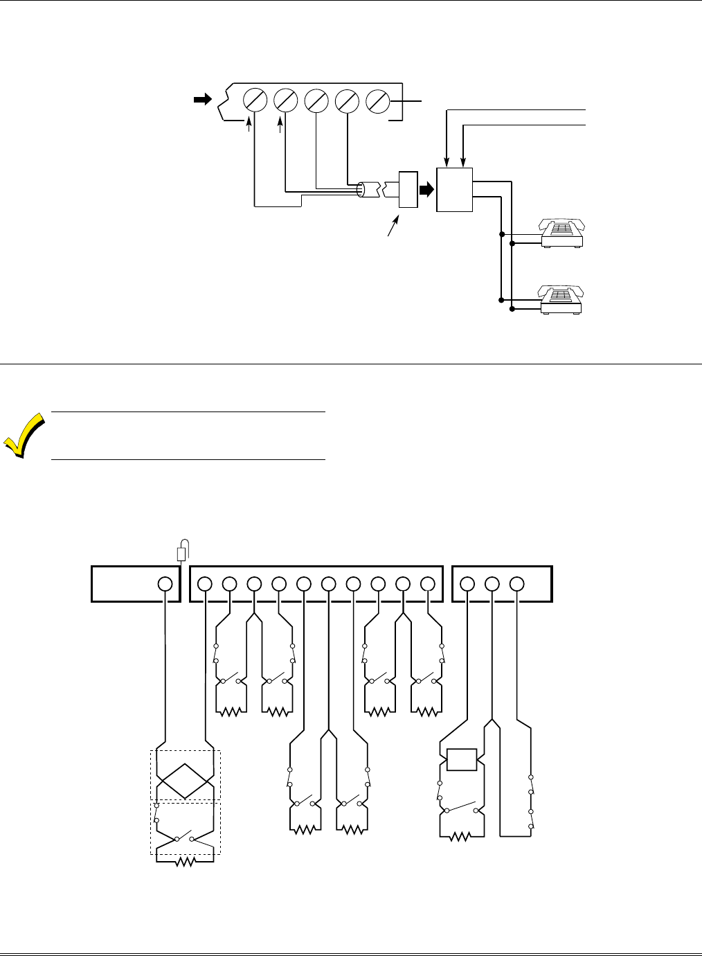
Wiring Burglary, Panic and Smoke Detector Devices to Zones 1-9
The maximum zone resistance is 100 ohms for
zones 1 and 8, and 300 ohms for all other
zones (excluding the 2K EOL resistor).
To wire burglary and panic devices to zones 1-9, connect
sensors/contacts to the hardwire zone terminals (10
through 23). See Figure 3-9. Connect N.C. and N.O.
devices as follows:
• Connect N.C. devices in series with the high (+)
side of the loop. The 2K EOL resistor must be
connected in series with the devices, following the
last device.
• Connect N.O. devices in parallel (across) the loop.
The 2K EOL resistor must be connected across the
loop wires at the last device.
++
-
N.C.
N.C.
N.O.
2k EOLR 2k EOLR
+-
++
-
N.C.
N.C.
2k EOLR 2k EOLR
++
-
N.C.
+
+
-
N.C.
N.C.
2k EOLR
SMOKE
Zone resistance (Excluding EOLR):
ZONE 1,8: 100 OHMS MAXIMUM
ALL OTHER ZONES: 300 OHMS MAXIMUM
ZONE 1
ZONE 2 ZONE 3 ZONE 4 ZONE 5 ZONE 6 ZONE 7 ZONE 8 ZONE 9
2-WIRE SMOKE
DETECTOR LOOP
(Also supports NO/NC Burg contacts)
Programmable Response
(Fast/Normal) Loop
LATCHING TYPE GLASS
BREAK DETECTORS
10 11 12 13 14 15 16 17 18 19 20 21 22 23
N.C.
N.O.
N.O. N.O.
2k EOLR
N.O. N.O.
N.O.
N.C.
N.O.
2k EOLR
2k EOLR
N.C.
GLASS
BREAK
Fire
Usage
Burg.
Usage
Red Jumper
Zone response time:
ZONES 1-8: 350mSec-500mSec
ZONE 9: Programmable for
Fast: 10mSec-15mSec
Normal: 350mSec-500mSec
(default response)
hw_zones-001-V0
Figure 3-9: Wiring Connections for Zones 1-9