


VISTA-40 Installation and Setup Guide
3-2
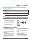
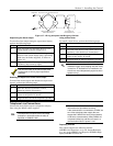
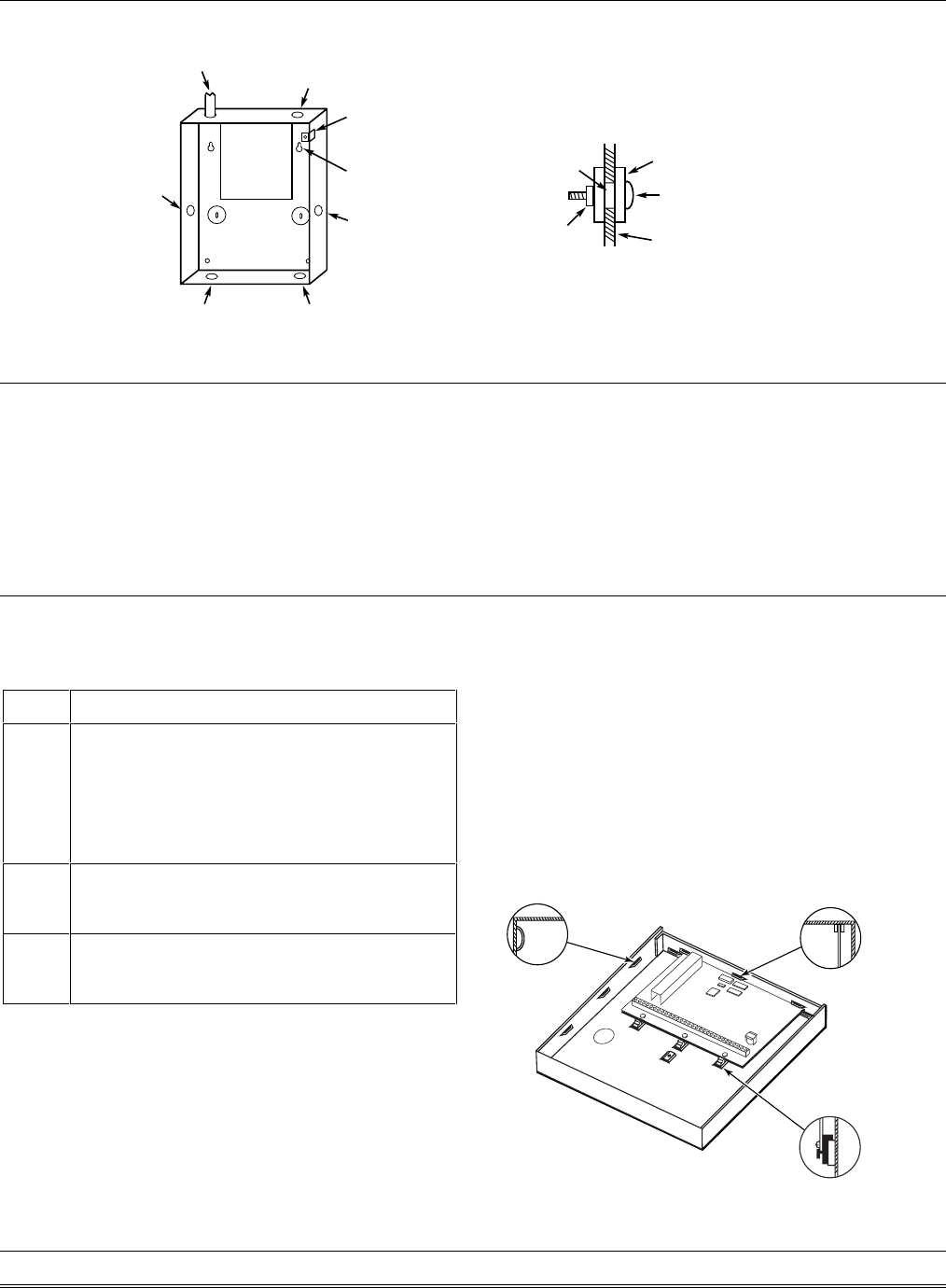
PC
BOARD
(Shows typical local Grade A listing installation)
RUN BELL WIRES
IN CONDUIT
PLUG THIS
KNOCKOUT
PLUG THIS
KNOCKOUT
PLUG THIS
KNOCKOUT
PLUG THIS
KNOCKOUT
RUN ALL REMAINING
WIRE THROUGH HERE
CLIP-ON DOOR
TAMPER SWITCH
CABINET
MOUNTING
HOLE
(4 PLACES)
TO PLUG AN UNUSED KNOCKOUT OPENING,
REMOVE KNOCKOUT AND INSTALL A PAIR OF
DISC PLUGS AND A CARRIAGE BOLT AS SHOWN.
KNOCKOUT
OPENING
HEX NUT AND
WASHER
DISC PLUGS (DIMPLES IN DISC
PLUG SHOULD REGISTER INSIDE
KNOCKOUT OPENING)
CARRIAGE BOLT
CABINET SIDE WALL
(OUTSIDE)
cabattack-001-V0
Figure 3-2: Cabinet Attack Resistance Considerations
Grade A Mercantile Safe and Vault Listing Guidelines
• Follow the guidelines given above for Grade A
Mercantile Premises listing.
• Mount a shock sensor such as Sentrol No. 5402 to
the control’s backbox. Follow the manufacturer’s
instructions for proper sensor mounting. This
sensor also must be wired to a hardwire zone.
• For safe and vault applications, a UL Listed
contact must be used inside the cabinet through
one of the knockouts for pry-off tamper purposes.
This sensor also must be wired to a hardwire zone.
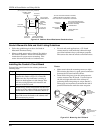
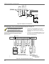
Installing the Control’s Circuit Board
To install the circuit board in the cabinet, perform the
following steps:
Step Action
1
Hang the three mounting clips on the raised
cabinet tabs. Refer to Figure 3-3 (Detail B).
Make sure the clip orientation is exactly as
shown in the diagram to avoid damage. This
will also avoid problems with insertion and
removal of the PC board.
2
Insert the top of the circuit board into the slots
at the top of the cabinet. Make certain that the
board rests in the slots as indicated (Detail A).
3
Swing the base of the board into the mounting
clips and secure the board to the cabinet with
the accompanying screws.
Notes:
• Make certain that the mounting screws are tight.
This ensures that there is a good ground connection
between the PC board and the cabinet.
• Dress field wiring away from the microprocessor
(center) section of the PC board. Use the loops on
the left and right sidewalls of the cabinet for
anchoring field wiring using tie wraps (Detail C).
These steps are important to minimize the risk of
panel RF interference with television reception.
+
+
+
DETAIL C
SIDE VIEW
OF SLOTS
DETAIL A
SIDE VIEW OF
BOARD INSERTED
INTO SLOTS
DETAIL B
SIDE VIEW OF SHORT
MOUNTING CLIPS
(TYP.)
hi_end_mnt-PCB
Figure 3-3: Mounting the PC Board