


3-1
SECTION 3
Installing the Control
•••••••••••••••••••••••••••••••••••••••••••••••••
This section describes the procedures for mounting and wiring the control panel and all the peripheral devices.
Mounting the Control Cabinet
To mount the control cabinet, perform the following steps:
Step Action
1 Before mounting the circuit board, remove the metal knockouts for the wiring entry that you will be using.
DO NOT ATTEMPT TO REMOVE THE KNOCKOUTS AFTER THE CIRCUIT BOARD HAS BEEN
INSTALLED.
2 Using fasteners or anchors (not supplied), mount the control cabinet to a sturdy wall in a clean, dry area
that is not readily accessible to the general public. The back of the cabinet has 4 holes for this purpose.
U
L
To provide certificated burglary service for UL installations, refer to the special requirements and Figure 3-2
Cabinet Attack Resistance Considerations to follow. For UL Commercial Burglary installations that require
ATTACK RESISTANCE, use the cabinet included in the VISTA-ULKT kit.
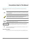
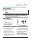
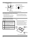
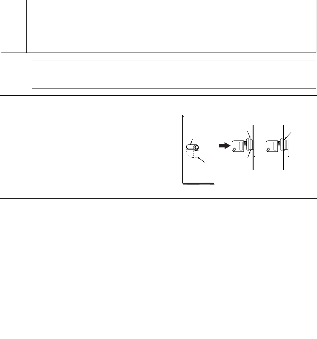
Installing the Cabinet Lock
1. Remove cabinet door, then remove the lock
knockout from the door. Insert the key into the
lock.
2. Position the lock in the hole, making certain
that the latch will make contact with the latch
bracket when the door is closed.
3. When correctly positioned, push the lock until
it is held securely by its snap tabs.
Use Part Number K4445 Lock (supplied).
CABINET DOOR
BOTTOM
LOCKED
UNLOCKED
cab_lock_snap-001-V0
ADEMCO
ADEMCO
PUSH
SNAP
TAB
SNAP
TAB
PUSH
ON LOCK
UNTIL IT
IS SEATED
SECURELY
STEP 2STEP 1
CHECK
POSITION
Figure 3-1: Installing the Lock
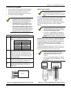
Grade A Mercantile Premises Listing Guidelines
• The panel door must be supervised. Mount the
clip-on tamper switch (supplied) to the cabinet’s
right side wall as shown in the diagram below, and
wire it to one of the hardwire zones.
• Use a bell with a tamper-protected housing such as
the AB12. The bell housing’s tamper switch and
inner tamper linings must also be wired to the
hardwire zone.
• Assign the tampers’ hardwire zone to a burglary
partition. Program the hardwire zone for day
trouble/night alarm (zone type 5) when only one
burglary partition is used. Program it for 24-hr.
audible alarm (zone type 7) when more than one
burglary partition is used.
• All wiring between the bell and panel must be run
in conduit. Remaining wires do not need to be run
in conduit.
• All wiring that is not run in conduit must exit from
the knockout openings on the bottom or back of the
cabinet.
• All unused knockouts must be plugged using the
disc plugs and carriage bolts (supplied), as
indicated in the diagram below.
• Fasten the cabinet door to the cabinet backbox
using the 18 one-inch-long Phillips-head screws
(supplied) after all wiring, programming, and
checkout procedures have been completed.