


Section 3 - Installing the Control
3-17
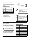
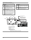
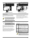
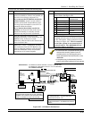
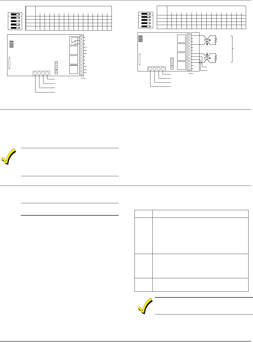
SWITCH 4204 ADDRESS SETTINGS
POSITION ("—" means "OFF")
0 1 2 3 4 5 6 7 8 9 10 11 12 13 14 15
2
ON — ON — ON — ON — ON — ON — ON — ON —
3
ON ON ——ON ON ——ON ON ——ON ON ——
4
ON ON ON ON ————ON ON ON ON ————
5
ON ON ON ON ON ON ON ON ————————
ON
12345
➞
➞
➞
➞
➞
13 14 15 16
C
NC
NO
OFF
➞
ON
➞
DIP SWITCH
FOR SETTING DEVICE ADDRESS
AND ENABLING/DISABLING TAMPER
➞➞
COVER TAMPER (REED) SWITCH
➞➞
TB1
4204
TB2
4-PIN CONSOLE PLUG
➞➞
121110987654321
C
NC
NO
C
NC
NO
C
NC
NO
▲
RELAY
3
RELAY
2
RELAY
1
RELAY
4
TYPICAL
(SHOWN "OFF")
EITHER OR BOTH
CAN BE USED
➞➞
➞➞
DATA IN
FROM CONTROL
(–) GROUND
DATA OUT
TO CONTROL
(+) 12V
YEL
BLK
GRN
RED
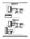
Figure 3-21: 4204 Relay Module
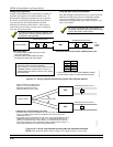
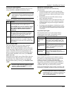
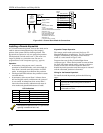
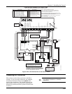
SWITCH 4204CF ADDRESS SETTINGS
POSITION ("—" means "OFF")
0 1 2 3 4 5 6 7 8 9 10 11 12 13 14 15
2
ON — ON — ON — ON — ON — ON — ON — ON —
3
ON ON ——ON ON ——ON ON ——ON ON ——
4
ON ON ON ON ————ON ON ON ON ————
5
ON ON ON ON ON ON ON ON ————————
ON
12345
➞
➞
➞
➞
➞
OFF
➞
ON
➞
13 14 15 16
NC
NC
DIP SWITCH
FOR SETTING DEVICE
ADDRESS AND
ENABLING/DISABLING
TAMPER
➞➞
COVER TAMPER (REED) SWITCH
➞➞
TB1
TB2
4-PIN CONSOLE PLUG
➞➞
121110987654321
NC
NC
NC
NC
▲
EITHER OR BOTH
CAN BE USED
➞➞
➞➞
DATA IN
FROM CONTROL
(–) GROUND
DATA OUT
TO CONTROL
YEL
BLK
GRN
RED
(+) 12V; SUPPLIES POWER TO MODULE
CIRCUITRY (INCLUDING NOTIFICATION
APPLIANCE RELAY COILS). CURRENT
DRAIN AT 12V IS: 25 mA + (80 mA PER
ACTIVE OUTPUT)
NOTIFICATION APPLIANCE AND
CONSOLE DATA OUTPUTS ARE
POWER LIMITED
–
+
NOTIFICATION
APPLIANCE B
2K EOLR
#610-7
POLARIZED
NOTIFICATION
APPLIANCE
–
+
NOTIFICATION
APPLIANCE A
2K EOLR
#610-7
}
–
+
POWER FOR
NOTIFICATION APPLIANCE A,
NOTIFICATION APPLIANCE B
8-28VDC OR VFW. UP TO 2.4A
DEPENDING ON BELL CURRENT
- ALARM POLARITY
SHOWN
- EACH OUTPUT
PROVIDES
STYLE Y
SUPERVISION
- EACH OUTPUT
RATED 1.2A MAX
- USE
NOTIFICATION
APPLIANCES
COMPATIBLE
WITH
NOTIFICATION
APPLIANCE
POWER SUPPLY
VOLTAGE
RATING
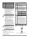
Figure 3-22: 4204CF Relay Module
Installing X10 Devices
X-10 devices are either plugged into standard AC
outlets or wired into the AC electrical system by a
licensed electrician, depending on the type of device
used.
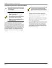
Note each device’s House and Unit Code
setup, as these codes will be used to program
the devices in Output Programming in #93
Menu Mode described in the Programming
Guide.
X-10 devices require the use of a 1361X10 transformer
in place of the regular 1361 transformer.
X-10 devices respond to “on” and “off” commands sent
from the panel through the 1361X10 transformer.
To connect the 1361X10 transformer, see Connecting the
Transformer, later in this section.
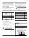
Installing the Ground Start Module
U
L
The Ground Start Module is not intended for
use in UL Listed applications.
Output 1 may be used to trigger an optional 675
Ground Start Module for installations having telephone
lines that require ground start instead of loop start
operation to obtain a dial tone from the telco central
office.
When the panel has a message to transmit to the
central station, it seizes the line, goes off hook, and then
triggers the 675 Module to connect the RING side of the
telephone line to earth ground. The panel causes the
module to break the connection between RING and
earth ground when it obtains a dial tone.
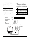
To install the 675 Ground Start Module, perform the
following steps:
Step Action
1 Determine which side of the telephone line
is the RING side by connecting the (+) lead
of a DC voltmeter to earth ground, and the
(-) lead to one side of the telephone line.
The wire that reads + 50VDC is the
RING side.
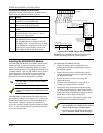
2 Connect the 675 Ground Start Module to
the panel’s J7 connector trigger output 1, to
auxiliary power, and to the RING side of
the telephone line as shown in Figure 3-23.
3
Program field 1✳46 Auxiliary Output
Enable with a [0].
You cannot use Output 1 for the Ground Start if
you are using it for Open/Close or an AAV
module.