


VISTA-40 Installation and Setup Guide
3-16
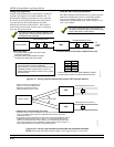
Transmitter Battery Life
Batteries in the wireless transmitters may last from 4
to 7 years, depending on the environment, usage, and
the specific wireless device being used. Factors such as
humidity, high or low temperatures, as well as large
swings in temperature may all reduce the actual
battery life in a given installation.
The wireless system can identify a true low battery
situation, thus allowing the dealer or user of the system
time to arrange a change of battery and maintain
protection for that point within the system.
Some transmitters (e.g., 5802, 5802CP, and 5803)
contain long-life but nonreplaceable batteries. At the
end of their life, the complete unit must be replaced
(and a new serial number enrolled at the control).
Button-type transmitters (e.g., 5801, 5802, 5802CP and
5803) should be periodically tested, as these
transmitters do not send supervisory check-in signals.
To test the transmitters using the Transmitter
ID Sniffer mode and the Go/NoGo Test Mode,
see SECTION 10: Testing the System for the
procedures.
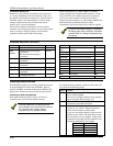
Compatible 5800 Series Transmitters
Model Product Input Type
5801 Panic Transmitter UR or RF
5802
5802CP
Pendant (Personal Emergency
Transmitter)
Belt Clip (Personal Emergency
Transmitter)
BR Only
5802MN Miniature (Personal Emergency
Transmitter)
UR or RF
5802MN2 Miniature (Personal Emergency
Transmitter)
UR or RF
5804 Wireless Key Transmitter BR Only
5804BD Wireless Key Bi-directional
Transmitter
BR Only
5804BDV Wireless Key Bi-directional
Transmitter with Voice
BR Only
Model Product Input Type
5806/5807/
5808
Wireless Photoelectric Smoke
Detectors
RF
5816 Door/Window Transmitter RF
5816MN Miniature Door/Window Transmitter
5816TEMP Temperature Sensor Transmitter
5817 Multi-Point Universal Transmitter RF
5818 Recessed Transmitter RF
5827 Wireless Keypad House ID
5827BD Wireless Bi-directional Keypad House ID
5849 Glassbreak Detector RF
5850 Glassbreak Detector RF
5890 PIR Detector RF
5890PI PIR Detector with Pet Immunity RF
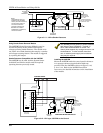
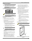
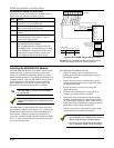
Installing Relay Devices
The VISTA-40 support up to 8 relays. Each device must
be programmed as to how to act (ACTION), when to
activate (START), and when to deactivate (STOP). The
4204 and/or X-10 devices may be used as relay devices.
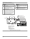
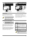
Installing the 4204 Relay Modules
Each 4204 module provides 4 relays with Form C
(normally open and normally closed) contacts.
The relay module will not operate until the
device address you have set the DIP switches
for is enabled in the control’s Device
Programming in the #93 Menu Mode.
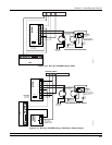
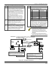
To install the relay modules, see Figures 3-21 and 3-22
and perform the following steps:
Step Action
1 Set the 4204 or 4204CF’s DIP switches for a
device address 01-15.
Do not use an address being used by another
device (keypads, RF receivers, etc.).
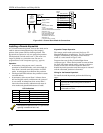
2 Mount the 4204 and 4204CF Modules per the
instructions provided with them.
Connect the module’s wire harness to the
control (6, 7, 8, and 9). Plug the connector
(other end of harness) to the module.
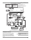
If you are mounting remotely, homerun each
module to the control. The table below shows
the maximum wire run lengths. Refer to the
instructions provided with the 4204CF for its
maximum permissible wire lengths.
Wire Gauge Maximum Length
#22 125 feet
#20 200 feet
#18 300 feet
#16 500 feet
3