


Section 3 - Installing the Control
3-19
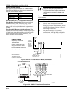
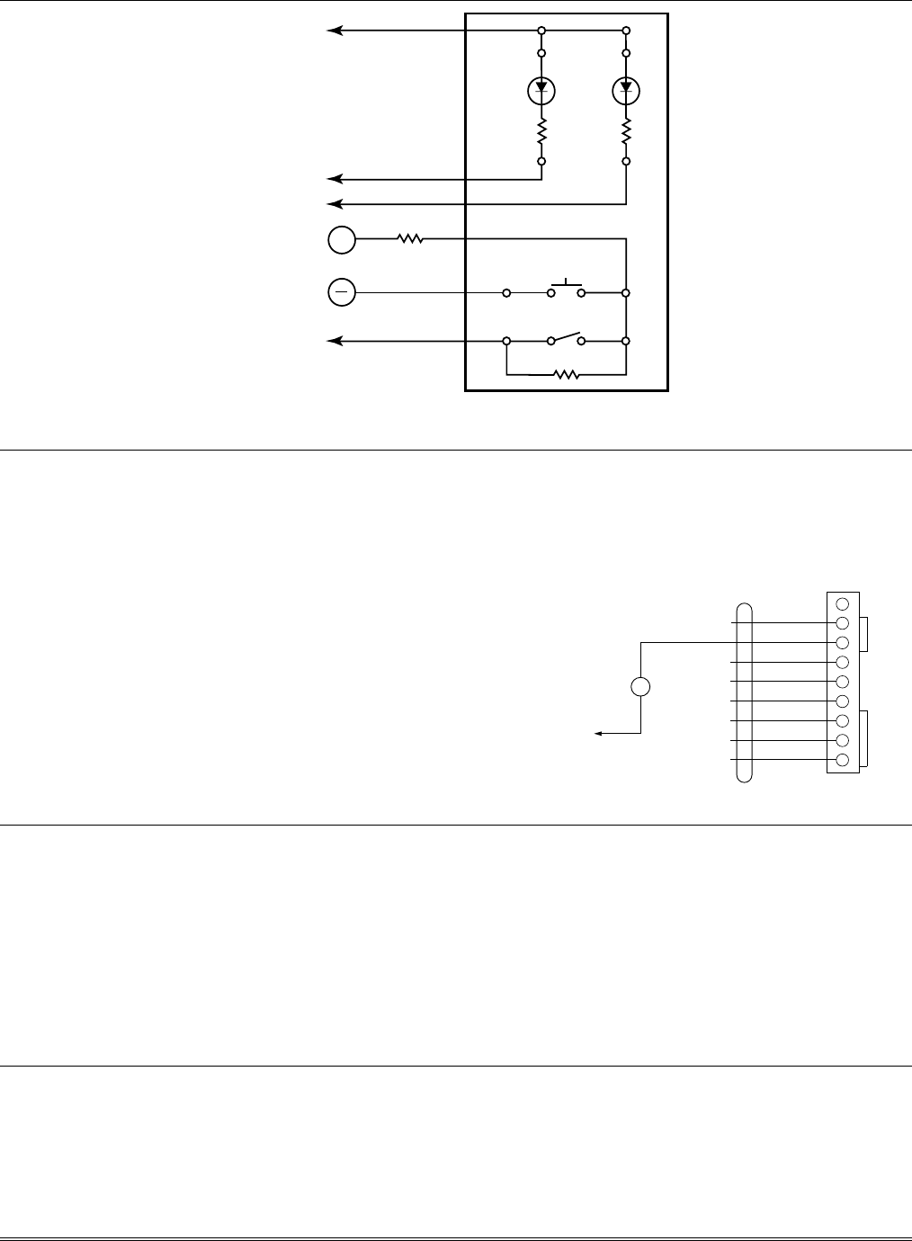
2K ELOR
2K ELOR
TAMPER SWITCH
(CONTACTS CLOSE WHEN
SWITCH DEPRESSED).
LOCK SWITCH
(NORMALLY OPEN)
+
TO J7 / OUT 2
TO J7 / OUT 4
TO AUX POWER
(TERMINAL 6)
ZONE
ZONE
TO ZONE 7 (+)
(TERMINAL 20)
YELLOW WHITE
GREEN
(READY)
RED
(ARMED)
RED BLACK
820
ohms
820
ohms
J7_keyswitch
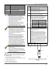
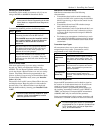
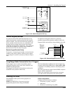
Figure 3-24: Remote Keyswitch Wiring
Remote Keypad Sounder
An optional Amseco PAL 328N Piezo Sounder can be
used to duplicate the sounds produced by the keypad’s
built-in sounder. The panel will remote all sounds (e.g.,
alarm, trouble, chime, entry/exit, etc.) produced by the
keypad’s built-in sounder except for the short beeps
associated with keypad key depression. One application
of this feature might be to produce chime sounds at a
distant location from the panel’s keypads.
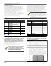
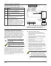
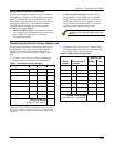
Remote Keypad Sounder Setup
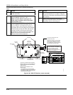
To setup for a remote keypad sounder, connect the piezo
sounder to the panel’s positive auxiliary power output
and to Output 1 on the J7 connector as shown in Figure
3-25.
To duplicate the keypad sounds for a particular
partition, program that partition number in field ✳15.
Program field 1✳46 Auxiliary Output Enable with a [2].
1 2 3 4 5 6 7 8 9
GRAY (GROUND)
YELLOW (OUT 1)
WHITE (GROUND)
RED (OUT 2)
GREEN (GROUND)
BROWN (OUT 3)
BLUE (GROUND)
BLACK (OUT 4)
J7 CONNECTOR
IF USED.
1. OUT 1 IS NO LONGER
USABLE FOR SMOKE
DETECTOR RESET
OR GROUND START
(SEE FIELD 1*46).
2. OUT 2 & 4 CAN NO LONGER
BE USED TO PROVIDE
ALARM TRIGGERS.
N/U
4142TR CABLE
BLACK
–
AMSECO PAL-328N
PIEZO SOUNDER
+
RED
TO AUX POWER +
TERMINAL 6
10mA CURRENT DRAIN)
J7_trigcon-001-V1
Figure 3-25: Remote Keypad Sounder Wiring
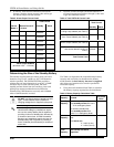
Long Range Radio Connected to the J7 Triggers
These triggers may be used to trip auxiliary alarm
signaling equipment such as the 7720, 7720ULF, and
7920SE Long Range Radios.
The triggers are common to all partitions and must be
enabled for each partition (field 2✳20).
The fire and burglary/audible panic alarm triggers are
normally LOW and go HIGH until a User Code + OFF
is entered in all enabled partition(s) that display these
conditions.
The silent panic/duress trigger latches HIGH, except for
duress, which is momentary.
Refer to the installation instructions that accompany
your radio for the connections to the control panel.
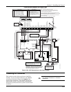
Installing a 4100SM
The 4100SM is used to print event log reports to a
serial printer.
NOTE: See SECTION 4: Programming for the
programming details when using the 4100SM.
Printer Configurations
Configure the serial printer as follows:
• 8 data bits, no parity, 1 stop bit
• 1200 baud
• Hardware handshaking using DTR.