


-
74
-
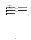
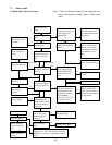
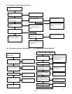
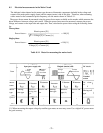
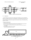
[In the case of 3-phase input series] [In the case of single-phase
input series]
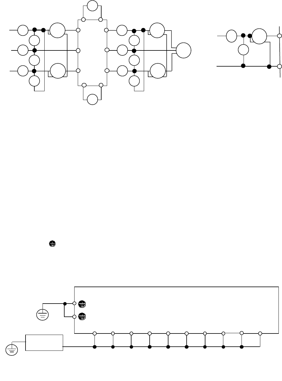
Figure 8-3-1 Diagram for connections of meters
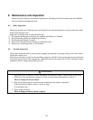
8-4 Insulation Test
As much as possible, do not test the drive with a megger because an insulation test was done at shipping from
the factory. If a megger test must be done, test as described below. If the test method is incorrect, there is a pos-
sibility of damaging the product. Incorrect use of test specifications for the dielectric strength test may damage
products like megger test. If the dielectric strength test must be conducted, contact your local distributor or near-
est GE Fuji’s sales office.
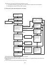
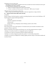
(1) Megger test for the main circuit
1) Test with a 500V dc megger.
2) If the test voltage is connected to the control circuit, remove all connection wires to the control circuit.
3) Connect the main circuit terminals using common wires as shown in Figure 8-4-1
4) Execute a megger test only between the common wire connected to the main circuit and the ground
(terminal G).
5) If the megger indicates 5MΩ or more, it is normal.
(This is the value measured with a drive only.)
Power supply
Figure 8-4-1 Megger Test
Symbols in parentheses ( ) are for the single-phase
230V series.
Drive
Power supply
Motor
W
R
M
V
V
W
A
W
V
V
A
V
V
U
A
U
+
L3/T
L2/S
L1/R
N(–)
P(+)
–
+
L2/N
L1/L
L1
FM
–
U
V
W
+
A
R
V
R
A
R
A
S
A
T
V
R
V
S
V
T
W
R
W
T
W
W
W
U
Drive
V
Drive
W
V
N(-)
P(+)
P(+)
P1
U
G
G
L3/T
(L2/N)
L2/S
(None)
L1/R
(L1/L)
Megger
3~