


-
19
-
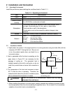
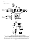
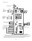
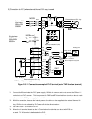
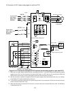
(2) Run/stop command terminal (FWD, REV)
FWD terminal is short-circuit to CM terminal in the factory. Pressing the RUN key on the keypad
panel can start forward operation. If function F02 is 0, short-circuit FWD and CM and press the
RUN key for forward operation, or short-circuit REV and CM for reverse operation. If function F02 is
1, then short-circuit FWD and CM for forward operation, or REV and CM for reverse operation.
Regardless of whether function F02 is set to 0 or 1, short-circuiting both FWD – CM and REV – CM
brings the drive to a deceleration-stop. Refer to F02 “Operation method” for details.
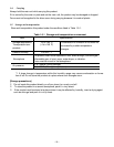
(3) Analog input terminal (13, 12, 11, C1)
Use these terminals to connect external input analog voltage and analog current and frequency
setting device (POT). For connecting a contact to this circuit, use a twin contact for fine current sig-
nal. Do not use a contact for terminal 11.
!
WARNING
1. The STOP key is valid only when the function has been set. Prepare an-
other switch for emergency stop. When the data of F02 is selecte “2” or “4”,
the operation cannot be stopped using the STOP key on the keypad panel,
otherwise accidents could occur.
*Note the following when wiring:
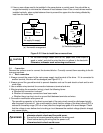
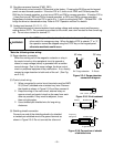
(1) Surge absorber connection
When the exciting coil of the magnetic contactor or relay in
the control circuit or drive peripheral circuit is opened or
closed, a surge voltage (noise) is generated with a sudden
current change. Due to this surge voltage, the drive control
circuit or peripheral equipment may malfunction. If so, directly
connect a surge absorber to both ends of the coil. (See Fig-
ure 2-3-4).)
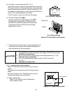
(2) Control circuit wiring
1 Wires connected to control circuit terminals must be AWG
20 (0.5mm
2
) shielded wire or twisted vinyl wire. Remove
the sheath as shown in Figure 2-3-5 and then connect it.
2 Keep the wiring of the main circuit, external relay se-
quence circuit and control circuit as far away from each
other as possible. If they must be adjacent, cross
them at right angles.
3 Use a twisted-pair shielded wire for long wiring
distances.
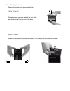
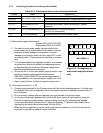
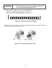
(3) Shielding sheath connection
Connect one end of the shielding sheath of a shielded
or twisted-pair shielded wire to the ground terminal as
shown in Figure 2-3-6. Do not connect the other end.
SK: Surge absorber D: Diode
Figure 2-3-4 Surge absorber
connection diagram
Figure 2-3-5 End treatment
Figure 2.3.6 Connection of sheath
of shielded wire
+
-
Ry
D
MC
SK
AC relay DC relay
0.24” ± 0.04” (6±1mm)
To ground terminal
To ground terminal
CM
13
12
11
Contact
Shielded wire
FWD
Frequency
setting POT
Shielded wire