


-
18
-
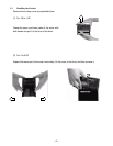
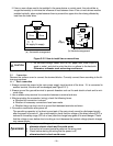
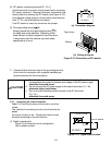
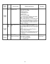
(3) DC reactor connecting terminal [P1, P(+)]
Use this terminal to connect a input power-factor correcting
DC reactor (optional). Remove the jumper connected in the
factory before connecting the DC reactor (see Figure 2-3-2).
Use diagonal cutting pliers to cut the surface cover barriers
from P1, P(+) terminals before connection.
If no DC reactor is used, do not remove the jumper.
(4) Drive grounding terminal[ G]
Always ground the drive grounding terminal [ G]
for safety and noise reduction. Grounding of the
metal frames of electric equipment has to be done
in accordance with the national and local safety
specifications in force.
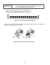
1 Connect a thick and short wire to the grounding terminal
of the drive for connection with a ground electrode pre-
pared exclusively for the drive system.
!
CAUTION
1. Check that the number of phases and the rated voltage of this product
correspond to the number of phases and voltage of the AC power supply,
otherwise fire could occur.
2. Do not connect the AC power supply to the output terminals (U, V, W),
otherwise injury could occur.
3. Do not connect a braking resistor directly to the DC terminals
P(+), N(-),
otherwise fire could occur.
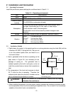
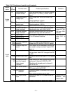
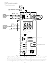
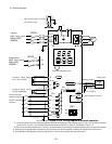
2-3-3 Connecting the control terminals
Table 2-3-2 lists the functions of the control circuit ter-
minals.
The method of connecting a control circuit terminal de-
pends
on how its function is set. Connect the control circuit
terminals according to the set functions.
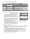
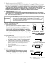
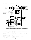
(1) Digital input terminal
Figure 2-3-3 shows the circuit configuration.
Use a reliable contact.
Top of drive
Barrier
(b) Cutting of barrier
Figure 2-3-2 Connection of DC reactor
(a) Connection diagram
Figure 2-3-3 Digital input terminal
P(+)
P1
AF-300C11
FWD or others
CM
4.7kΩ
+24 to +27Vdc
AF-300C11