


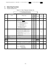
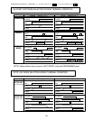
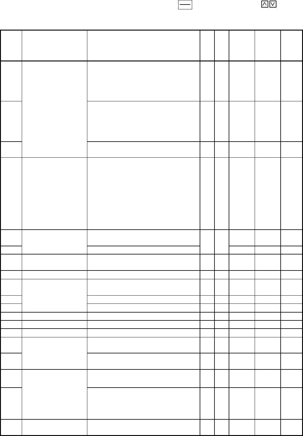
Change during operation: N = impossible, Y* = possible (enabled by using ),
Y
= possible (enabled by using
)
-
34
-
FUNC
DATA
Func-
tion
code
No.
Name Setting range
Unit
Min.
unit
Factory
setting
Change
during
operation
User
setting
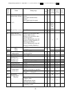
F10
Electronic thermal
overload relay (Select)
0:Inactive
1:Active
(for 4-pole standard motor)
2:Active
(for 4-pole forced air motor)
-
-
1 Y*
F11
(Level) 20 to 135% of drive rated current
A 0.01
Typical
value of
GE 4-
pole
motor
Y*
F12
(Thermal time constant)
0.5 to 10.0min
min 0.1 5.0 Y*
F14
Restart after mo-
mentary power failure
0:Inactive (Trip and alarm when
power failure occurs)
1:Inactive (Trip and alarm when
power recovers)
2:Active (Momentarily stops and
restarts at setting frequency of
before power failure)
3:Active (Momentarily stops and
restarts at starting frequency)
-
-
0
N
F15
Frequency limiter
(High)
0 to 120Hz
70 Y
F16
(Low) 0 to 120Hz
Hz 1
0 Y
F17
Gain (for frequency
setting signal)
0: For 0 to +10Vdc,
1: For 0 to +5Vdc
-
-
0
N
F18
Bias frequency -120 to 120Hz
Hz 1 0 Y
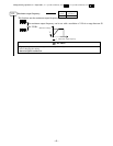
F20
DC injection brake
(Starting freq.)
Fixed to 3Hz
Hz
-
3.0
-
F21
(Braking level) 0 to 100%
% 1 0 Y
F22
(Braking time) 0.0 s (Inactive), 0.1 to 30.0 s
s 0.1 0.0 Y
F23
Starting frequency 1 to 6Hz
Hz 1 1
N
F24
-
Data cannot be changed.
-
-
0.0
-
F25
Stop frequency 1 to 6Hz
Hz 1 1
N
F26
0 to 15kHz
0.75kHz is set when 0 is specified
kHz 1 2 Y
F27
Motor sound
(carrier freq.)
(sound tone )
0: Level 0 1: Level 1
2: Level 2 3: Level 3
-
-
0 Y
F30 FM terminal
(Voltage adjust)
0 to 200%
% 1 100
Y
F31
(Function) 0: Output frequency
1: Output current
2: PID feedback amount
3: DC link circuit voltage
-
-
0 Y*
F36
30Ry operation mode 0: Excited when tripped
1: Normally excited
-
-
0
N