


-
1
-
Safety Instructions
Read this operation manual carefully and familiarize yourself with the operation of the drive be-
fore installation, connection (wiring), operation or maintenance and inspection of the device. Be
familiar with the drive, safety information, and safety signs before using the drive.
In this instruction manual, safety signs are classified into the following categories.
!
WARNING Improper operation may result in death of serious injury.
!
CAUTION Improper operation may result in slight to medium injury or property damage.
Note: More serious situations than those covered by the CAUTION sign can result depending on
the circumstances. It is important that you always follow the instructions
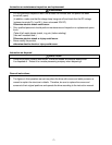
Compliance with UL/cUL standards [Applicable to products with UL/cUL mark]
!
CAUTION
1. [WARNING] Take care of electric shock. Be sure to turn the drive off before starting work.
2. [CAUTION] When the charge lamp is lit, the drive is still charged at a dangerous voltage.
3. [WARNING] There are two or more live parts inside the drive.
4. The drive is approved as a part used inside a panel. Install it inside a panel.
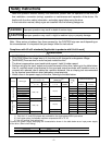
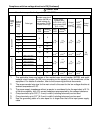
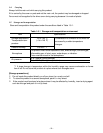
5. Perform wiring to the input, output and control terminals of the drive, referring to the table below.
Use UL certified round crimp terminal to the input and output terminals with insulation cover or
covered with reduced tube to obtain the insulation distance. Use a crimping tool recommended
by the terminal manufacturer when fabricating crimp terminals.
6. Install a fuse in the power supply to the drive, referring to the table below.
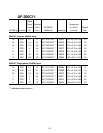
1) Only the L1/L and L2/N phases are provided for the single-phase 230V input series.
2) Use copper wires of allowable maximum temperature 60 or 75 °C.
3) Use UL certified "fast acting fuse."
Connect the power supply satisfying the characteristics shown in the table below as an input power supply
of the drive. (Short circuit rating)
Tightening torque
Lb • Inch[N • m]
Applicable wire diameter
[AWG] (mm
2
)
2)
Recommended fuse
Voltage Drive type
L1/R, L2/S, L3/T
1)
U. V. W
Control
section
L1/R, L2/S, L3/T
1)
U. V. W
Control
section
Fuse
[A]
3)
Gould
Company
Bussmann
Company
6KC1123F12X1** 3 A4J3 JKS3
6KC1123F25X1** 6 A4J6 JKS6
6KC1123F50X1** 10 A4J10 JKS10
6KC1123001X1** 15 A4J15 JKS15
6KC1123002X1**
14 (2.1)
20 A4J20 JKS20
6KC1123003X1**
10.6 (1.2)
12 (3.3) 30 A4J30 JKS30
3-phase 230V input
6KC1123005X1** 15.9 (1.8) 10 (5.3) 40 A4J40 JKS40
6KC1121F12X1** 6 A4J6 JKS6
6KC1121F25X1** 6 A4J6 JKS6
6KC1121F50X1** 10 A4J10 JKS10
6KC1121001X1**
14 (2.1)
15 A4J15 JKS15
6KC1121002X1**
10.6 (1.2)
12 (3.3) 30 A4J30 JKS30
Single-phase 230V
input
6KC1121003X1** 15.9 (1.8)
3.5
(0.4)
10 (5.3)
20
(0.5)
40 A4J40 JKS40
Drive type Input max. volta Input current
3 Phase input AC230V
Single phase input AC240V
5,000 A or less