


-
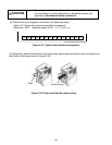
24
-
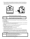
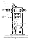
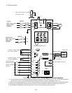
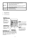
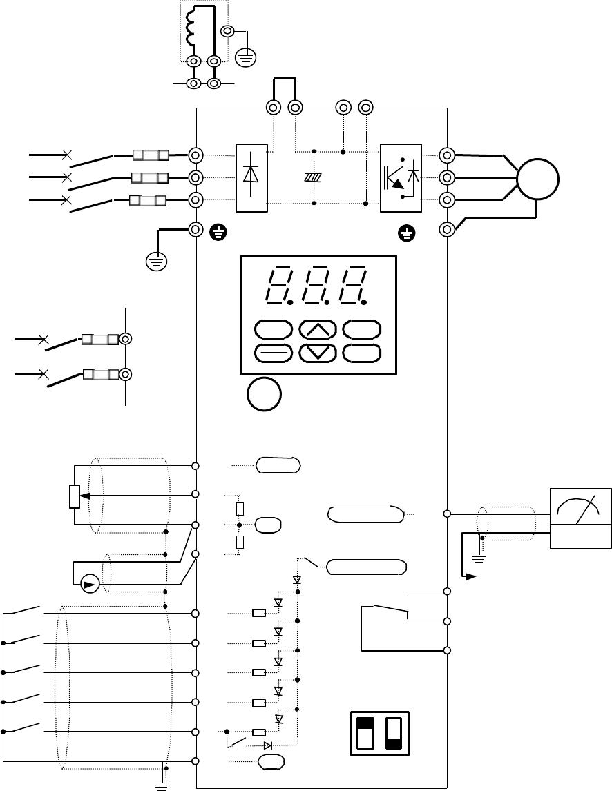
2) External operation
*1
Use this connection to start, stop the operation and set the frequency with external signals. 0 to +10V dc can be set while
function F01 is set to 1 and 4 to 20mA can be set while function F01 is set to 2. Set function F02 to 1~4.
*2 Remove the jumper between the P1 and P(+) terminals before connecting the optional power-factor correcting DC reactor.
*3 Connect the surge absorber in parallel to coils (such as coils of the magnetic contactor and solenoid) near the drive.
*4 Use twisted or shielded wire as control signal wire. Connect the shield to the ground terminal.
12
V
U
W
13
FWD
11
X1
REV
CM
X3
30C
30B
30A
X2
L2/S
L1/R
L3/T
P1
P(+) N(-) P(+)
M
FM
C1
P1
P(+)
When power-factor correct
ing
DC reactor is used
E
MCCB
*2
Frequency setting POT (VR)
+10Vdc
250Ω
22k
Ω
Pulse output
0V
0V
Reverse operation
command
Forward operation
command Forward
Analog monitor
Alarm output for any fault
To 11 terminal
Analog meter
G
G
+24 to +27Vdc
Figure 2-3-10 Wiring diagram of external operation
To ground terminal
To ground terminal
Frequency setting current
input (4 to 20mAdc)
Frequency setting voltage
input (0 to +10Vdc)
3-phase
230V input series
200 to 230V
50/60Hz
X3
EXT
INT
PLC
SW7
2 1
4.7kΩ
Single-phase
200V input series
200 to 240V
50/60Hz
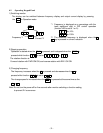
STOP
RUN
PRG
RESET
FUNC
DATA
INT
EXT
PLC
X3
L1/L
L2/N
MCCB
3~
Fuse