


-
27
-
2-4 Others
2-4-1 Harmonic component
A harmonic component which may influence the phase-advance capacitor and generator is included
in the drive input current. If necessary , connect a power-factor correcting DC reactor (DCR) (option)
for the drive.
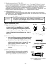
2-4-2 Noise
When noise generated from the drive may affect peripheral equipment, and noise generated from pe-
ripheral equipment may malfunction the drive, the following basic countermeasures should be taken.
1. When noise affects other devices via power and ground wires
· Separate the ground of the drive and that of the affected device.
· Connect a noise filter to the drive power wire.
· Use an isolation transformer to separate the power supply of the drive and that of the affected
device.
2) When another device is affected by induction or radiation
· Separate the main circuit wiring of the drive from the control wiring and wiring of the affected de-
vice.
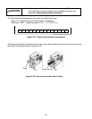
· Encase the drive main circuit wiring in a metal tube and ground the metal tube near the drive.
· Encase the drive in a metal rack and ground the rack.
· Connect a noise filter to the drive power wire.
3) When noise generated from peripheral equipment affects the drive
· Use twisted or twisted-pair shielded wires for the drive control wiring. Ground the shields.
· Connect a surge absorber in parallel to the coil of the magnetic contactor and solenoid .
· If the power supply includes much distortion of the waveform or surge, connect an impedance
matching AC reactor for coordination of power supply.
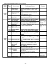
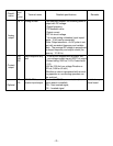
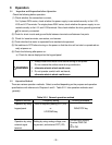
2-4-3 Leakage current
Leakage current flows through the drive I-O wiring and motor stray capacitance when the drive
transistor is turned on and off. Table 2-3-3 lists the countermeasures for the problems caused by the
leakage current.
Table 2-3-3 Countermeasures for leakage current
Problem Countermeasures
1 Trip of earth leakage circuit breaker
on main power supply side
Set the carrier frequency lower.
Shorten the wiring between the drive and motor.
Increase the ELCB/RCD sensitivity current.
Replace the ELCB/RCD with an ELCB/RCD that is de-
signed for high frequencies.
2 Trip of external thermal O/L relay
Set the carrier frequency lower.
Increase the thermal O/L relay set value.
Use the drive electronic thermal O/L relay.