


-
73
-
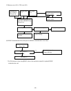
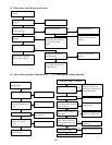
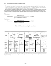
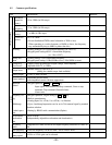
8-3 Electrical measurements in the Main Circuit
The indicated values depend on the meter types because of harmonic components included in the voltage and
current of the main power supply (input) and the output (motor) side of the drive. Therefore, when measuring
with a meter for the commercial power frequency, use the meters shown in Table 8-3-1.
The power-factor cannot be measured using the power-factor meter available on the market which measures the
phase difference between voltage and current. When the power-factor must be measured, measure the power,
voltage, and current on the input side and output side. Then, calculate the power-factor using the following formu-
las:
Three-phase
Single-phase
Table 8-3-1 Meter for measuring the main circuit
(*1) When measuring the output voltage by rectifier type meter, an error may occur. Use a digital AC power meter
for good accuracy.
Power factor =
Electric power [W]
3 x Voltage [V] x Current [A]
x 100 [%]
Electric power [W]
Voltage [V] x Current [A]
x 100 [%]
Power factor =
Moving-coil
type
Moving-
iron type
Rectifier
type (*1)
Power me-
ter
Power me-
ter
Rectifier or
moving-iron
type
Moving-
iron type
DC voltm
e-
ter
V
Wattmeter Wattmeter Voltmeter
Voltmeter
Ammeter
Ammeter Ammeter
Symbol
Meter
type
Meter
name
Terminal
section
DC circuit
Current
waveform
Current
waveform
Voltage
waveform
Output (motor) side
Input (power supply) side
Item
- -
Voltage
waveform