


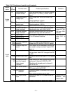
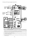
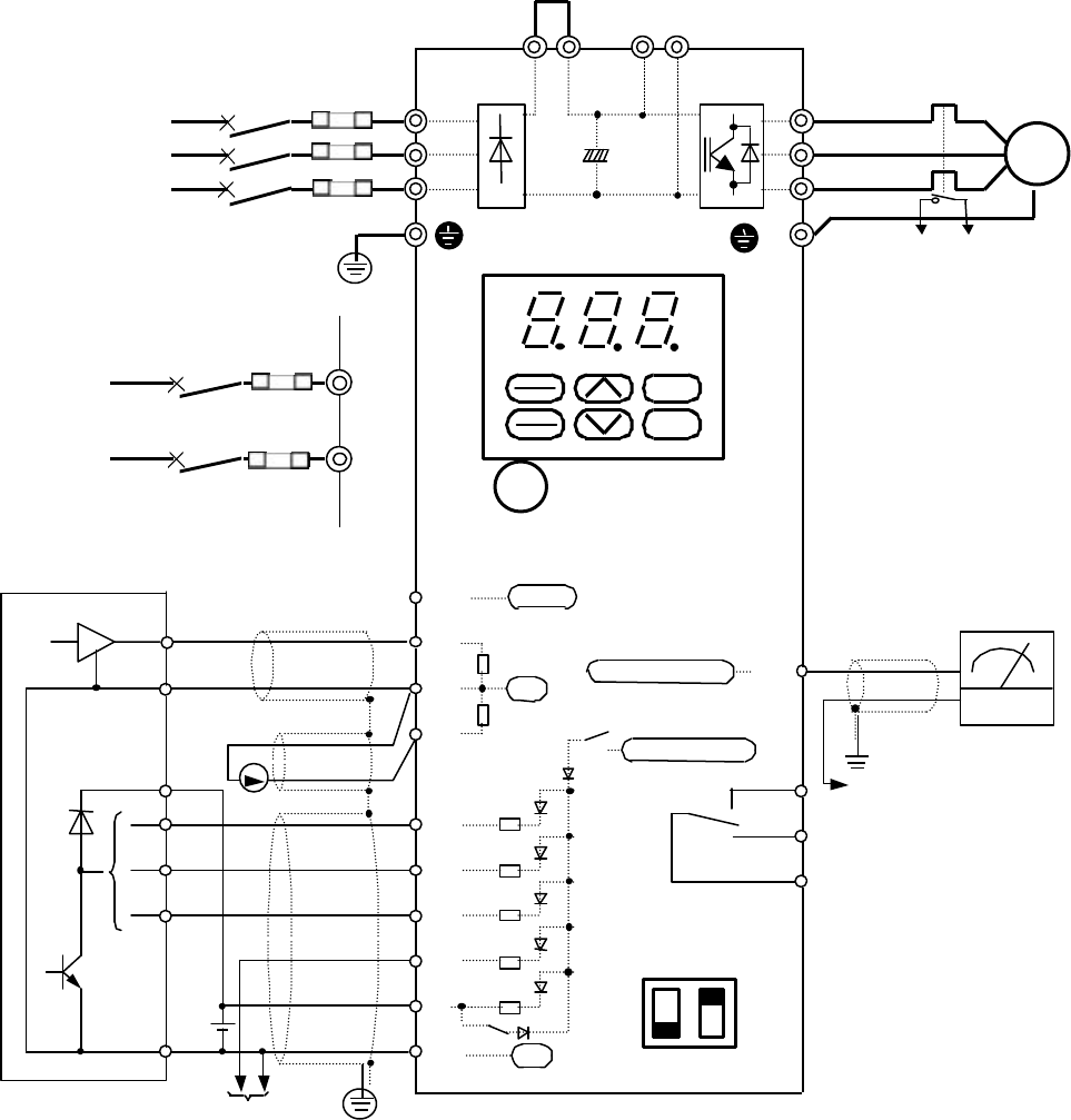
-
26
-
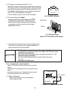
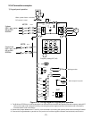
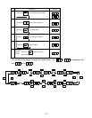
4) Connection to PLC (when analog signal is input from PLC)
12
V
U
W
13
FWD
11
X1
REV
CM
X3
30C
30B
30A
X2
(THR)
L2/S
L1/R
L3/T
P1
P(+)
N(-)
P(+)
M
FM
C1
MCCB
Frequency setting voltage input
+10Vdc
250Ω
4.7kΩ
22kΩ
Pulse output
0V
0V
Analog monitor
Alarm output for any fault
To 11 terminal
Analog meter
G
G
+24 to +27Vdc
P L C
24Vdc
To external thermal relay
External thermal relay
To X2 terminal
To CM terminal
X3
EXT
INT
PLC
SW7
2 1
*1 When the PLC power supply common may be connected to the drive 11 terminal to input ana
log frequency setting
signals from the PLC, use this connection and set the SW7 switch 1 to EXT and 2 to PLC to prevent the FWD and
REV terminals from turning on due to sneak path current when the PLC power is turned off.
*2
With this connection, the power is supplied from the PLC power supply to the external thermal O/L relay. So, OH2 trip
is activated by PLC power-off with the drive turned on.
*3 To prevent drive trip with OH2 when the PLC power being turned off, do not select the THR ter
minal function and use
the drive electronic thermal O/L relay.
*4 When the X3 terminal is used as the PLC terminal, no function that can be set with E03 can be use
d. The X3 terminal
is dedicated to the PLC.
24 V dc : PLC power supply
Figure 2-3-12 Connection example of PLC terminal (when analog signal is input from PLC)
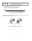
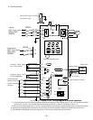
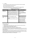
To ground terminal
L1/L
L2/N
3-phase 230V
input series
200 to 230V
50/60Hz
Single-phase
230V input series
200 to 240V
50/60Hz
MCCB
INT
EXT
PLC
X3
STOP
RUN
PRG
RESET
FUNC
DATA
3~
FUSE
FUSE