


-
17
-
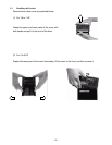
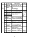
2-3-2 Connecting the main circuit and ground terminals
Table 2-3-1 Functions of main circuit and ground terminals
Symbol Name Explanation
L1/R,L2/S,L3/T Connects 3-phase power.(3-phase 230V input)
L1/L,L2/N
Main power supply input
Connects single-phase power. (Single-phase 230V input)
U, V, W Drive output Connects 3-phase motor.
P1, P(+) For connection of DC
reactor
Connects input power- factor correcting DC reactor
(optional).
P(+), N(-) For DC intermediate circuit Connected to DC link circuit terminal
(for DC bus connection).
G For drive grounding Ground terminal for drive chassis (case).
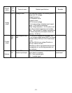
(1) Main power supply input terminal
3-phase 230V [L1/R,L2/S,L3/T]
Single-phase 230V [L1/L,L2/N]
1 Connect the main power supply input terminals to the
power supply via a molded case circuit breaker for circuit
protection or earth leakage circuit breaker. An earth-
leakage circuit breaker which can also detect DC current
is recommended. Phase-sequence matching is unneces-
sary.
2 It is recommended that a magnetic contactor is connected
to prevent any failure or accident from becoming serious
by disconnecting the drive from the power supply when
the drive protective function operates.
3 Do not turn on or off the main power supply to start or stop
the drive; instead, use the control circuit terminal
FWD/REV or the RUN/STOP key on the keypad panel. If
it is unavoidable to turn the main power supply on or off to
start or stop the drive, it must not exceed once per hour.
(2) Drive output terminal [U, V, W]
1 Connect these terminals to the 3-phase motor with the correct phase-sequence. If a motor rota-
tion direction does not correspond to the correct rotation direction, exchange any two of the U, V,
and W phases.
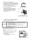
2 Do not connect a phase-advance capacitor or surge absorber to the drive output.
3 A very long wiring length between the drive and the motor causes a high frequency current to
flow due to floating capacity between cables, making the drive trip, increasing the leakage
current and deteriorating the accuracy in the current display. To prevent such trouble, the wir-
ing length to the motor should not exceed 165 feet (50 m).
When the drive is operated in the low noise mode (carrier frequency: 8 to 15 kHz) and the wir-
ing length is long, add an optional output circuit filter.
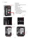
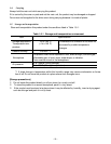
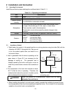
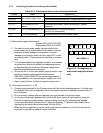
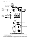
Figure 2-3-1 Arrangement of
main circuit and ground termi-
nals
P(+)
P1 L3/T
L2/S
G
G
L1/R
W V U N(-) P(+)
AF-300C11
For 3-phase 230V input
For single-phase 230V input
P(+)
P1 L2/N
G
L1/L