


190-01007-A1 System Maintenance Manual GTN 6XX/7XX Part 23 AML STC
Rev. 7 Page 6-19
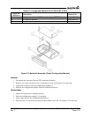
TVS2 Replacement
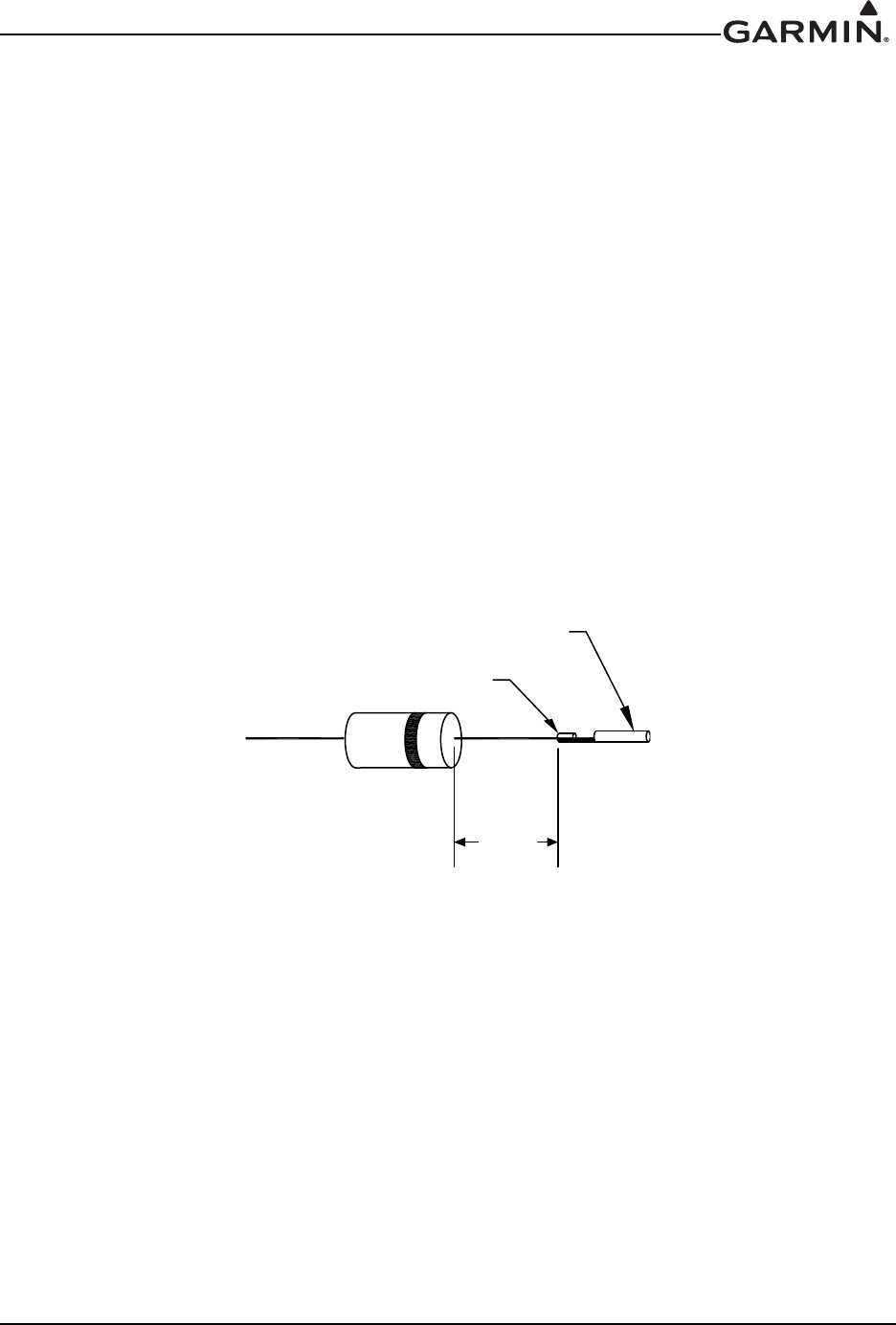
1. When installing new TVSs, cut the leads to 0.75 +0.00/-0.10" on both sides.
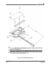
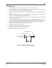
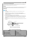
2. Crimp and solder each of the TVS banded side (cathode) leads to their specific sockets (refer to
Figure 6-10), and insert into the 4-pin connector with sockets.
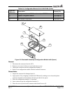
3. Install heat shrink around the four TVSs – this will help to hold them in place during the following
steps.
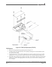
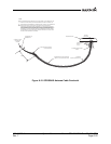
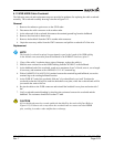
4. Solder the un-banded end of the TVS assembly together as shown in Figure 6-11 onto a length of
18 AWG wire. Attach a terminal lug onto the wire end.
5. Carefully remove heat shrink installed in Step 3 from the TVS ensuring not to cut the insulation on
the wire under the heat shrink.
6. Attach an appropriately sized section of heat shrink to cover the soldered TVS leads and four TVS
pieces. A second appropriately sized (larger) section of heat shrink should then be attached to
shrink over the 4-pin connector with sockets and back over the four TVSs. These two pieces of
heat shrink should overlap along the entire length of the TVSs.
7. Mate the four-pin connector together.
8. Reconnect the power end of the assembly to the power bus
9. Reconnect the ground end of the assembly to ground.
10. Perform a polarity check per Section 6.9.2.1.
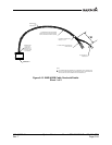
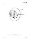
Figure 6-10. Detail of TVS Pin Assembly
0$;
62&.(7&217$&7
&5,03$1'62/'(5