


190-01007-A1 System Maintenance Manual GTN 6XX/7XX Part 23 AML STC
Rev. 7 Page 4-5
4.5.2 GTN (Composite Aircraft)
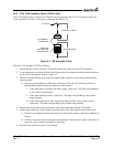
Perform an electrical bonding check as follows:
1. Remove the GTN 6XX or GTN 7XX from the mounting rack.
2. Remove the backplate assembly from the rack.
NOTE
For GTN 7XX only, if the GMA 35 is installed, it must be removed from its rack and the
GMA 35 backplate assembly must be removed prior to performing Step 3.
3. Measure the resistance between the mounting rack and the instrument panel, verify it is less than
or equal to 10 milliohms.
NOTE
A bonding test failure may occur if a fastener is not secured to the specified torque value.
For installations that use screws in lieu of rivets to secure the rack to surrounding
structure, verify that the screws are torqued to the appropriate value before proceeding to
remove the rack. See Section 4.4 for torque values.
In the event of bonding test failure, remove the GTN rack and clean the attachment points with a bonding
brush at both the GTN rack and the aircraft and reattach the rack to the rails in the panel. Re-verify the
resistance between the mounting rack and the instrument panel and ensure that the resistance is less than or
equal to 5 milliohms.
4. Reinstall the backplate assembly and reinstall the GTN in the mounting rack.