


190-01007-A1 System Maintenance Manual GTN 6XX/7XX Part 23 AML STC
Rev. 7 Page 6-14
6.8 GTN Fan
CAUTION
To avoid damage to the GTN, take precautions to prevent Electro-Static Discharge (ESD)
when handling the GTN, connectors, fan, and associated wiring. ESD damage can be
prevented by touching an object that is of the same electrical potential as the GTN before
handling the GTN itself.
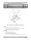
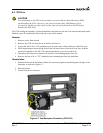
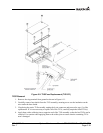
The GTN cooling fan assembly is located behind the rack relative to the unit. Fan removal and replacement
details for specific installations fall outside the scope of this manual.
Removal
1. Remove power from aircraft.
2. Remove the GTN unit from the rack. Refer to Section 6.1.
3.
Loo
sen the four 4-40 x 0.25" panhead screws at each corner of the inside rear wall of the rack.
4. While depressing the metal spring at the lower left hand corner of the rack’s rear face, slide the
connector backplate to the left. The connector backplate is now free of the rack.
5. Disconnect the fan power connector. Be careful to avoid damaging the fan wires.
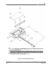
6.
Remov
e the four 4-40 x 1.375" panhead screws attaching the fan to the backplate.
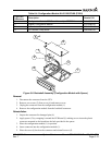
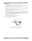
Reinstallation
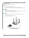
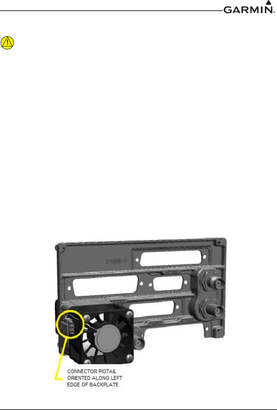
1. Position the fan on the backplate with the fan connector pigtail oriented along the left edge of the
backplate, as shown in Figure 6-7.
2. Reinstall screws.
3. Connect fan power connector.
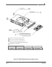
Figure 6-7. Fan/Backplate Orientation (GTN 7XX)