190-01007-A1 System Maintenance Manual GTN 6XX/7XX Part 23 AML STC
Rev. 7 Page 6-12
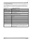
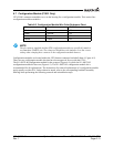
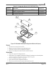
Table 6-3. Configuration Module Kit 011-00979-03 (P1001)
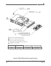
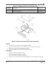
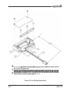
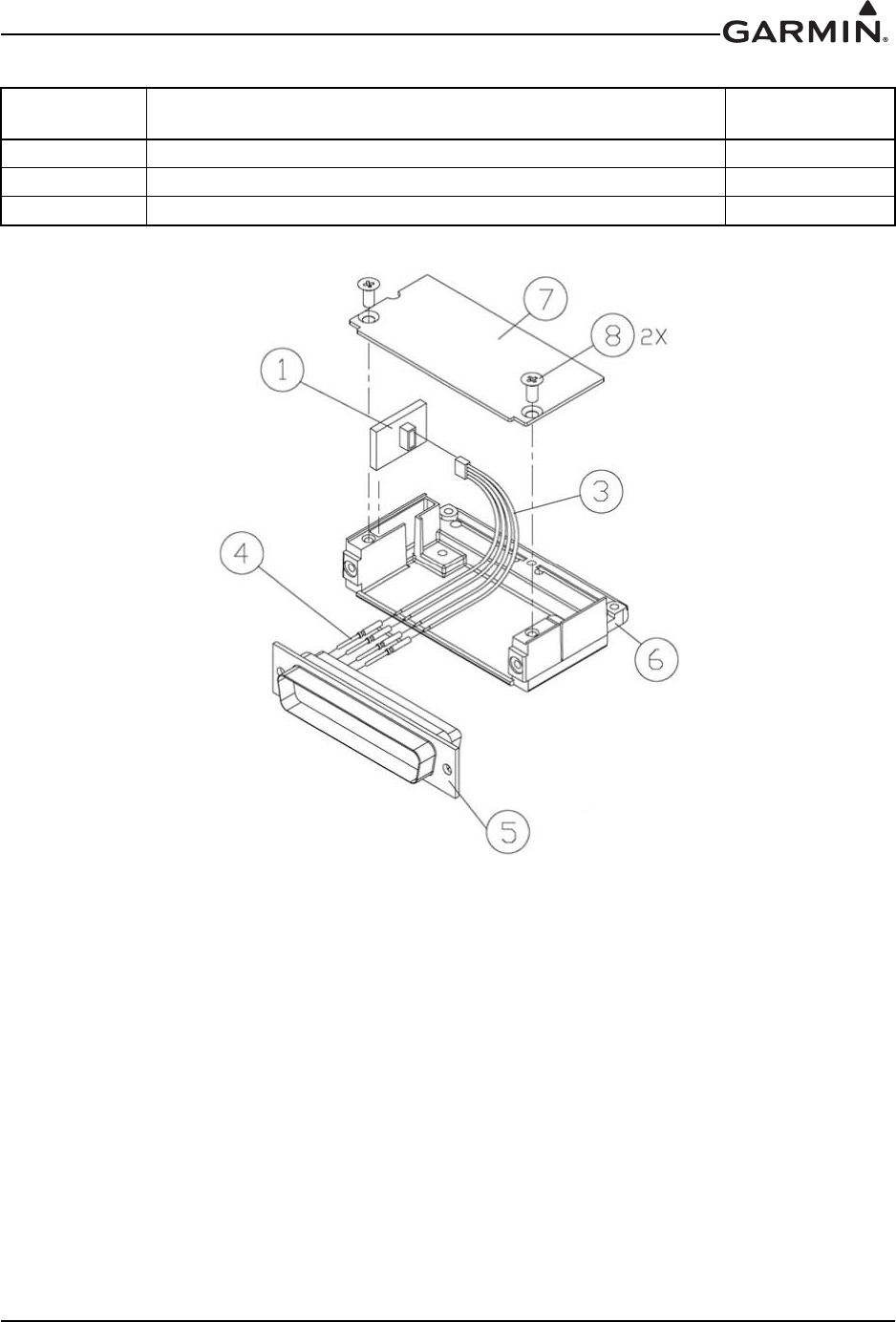
Figure 6-5. Backshell Assembly (Potted Configuration Module)
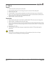
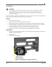
Removal
1. Disconnect the connector from the GTN backplate assembly.
2. Remove two screws (8) from cover (7) and remove cover. See Figure 6-5 for this step.
3. Unplug the connector from the configuration module (1).
4. Remove the configuration module from the backshell connector.
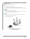
Reinstallation
1. Inspect the connector for damaged pins (4).
2. Place the configuration module (1) in position.
3. Insert connector into the configuration module (1).
4. Place the cover (7) back on the connector and reinstall screws (8). See Figure 6-5 for this step.
Figure 6-5
Reference
Description Garmin P/N
1 Configuration Module, PCB Board Assembly w/EEPROM 011-02178-00
3 4-Conductor Harness 325-00122-00
4 Pin Contact, Crimp, #22D 336-00021-00


