


190-01007-A1 System Maintenance Manual GTN 6XX/7XX Part 23 AML STC
Rev. 7 Page 6-18
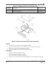
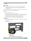
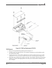
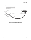
Figure 6-9. TVS/Fuse Replacement (TVS1/F1)
TVS2 Removal
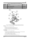
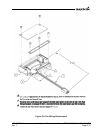
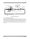
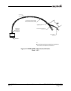
1. Remove the ring terminal from ground as shown in Figure 6-11.
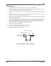
2. Carefully remove heat shrink from the TVS assembly, ensuring not to cut the insulation on
the
wire under the heat shrink.
3.
If replacing the entire TVS assembly, unplug the 4-pin connector and proceed
to step (1) of the
replacement. If it is
not necessary to replace all of the TVSs, carefully unpin the failed TVS(s).
4. Apply heat with a soldering iron to opposite end of the TVS assembly so that the ba
d TVSs can be
removed. Us
e caution when applying heat to the solder joint to ensure that the remaini
ng TVSs
aren’
t damaged.