


190-01007-A1 System Maintenance Manual GTN 6XX/7XX Part 23 AML STC
Rev. 7 Page 6-13
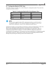
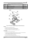
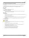
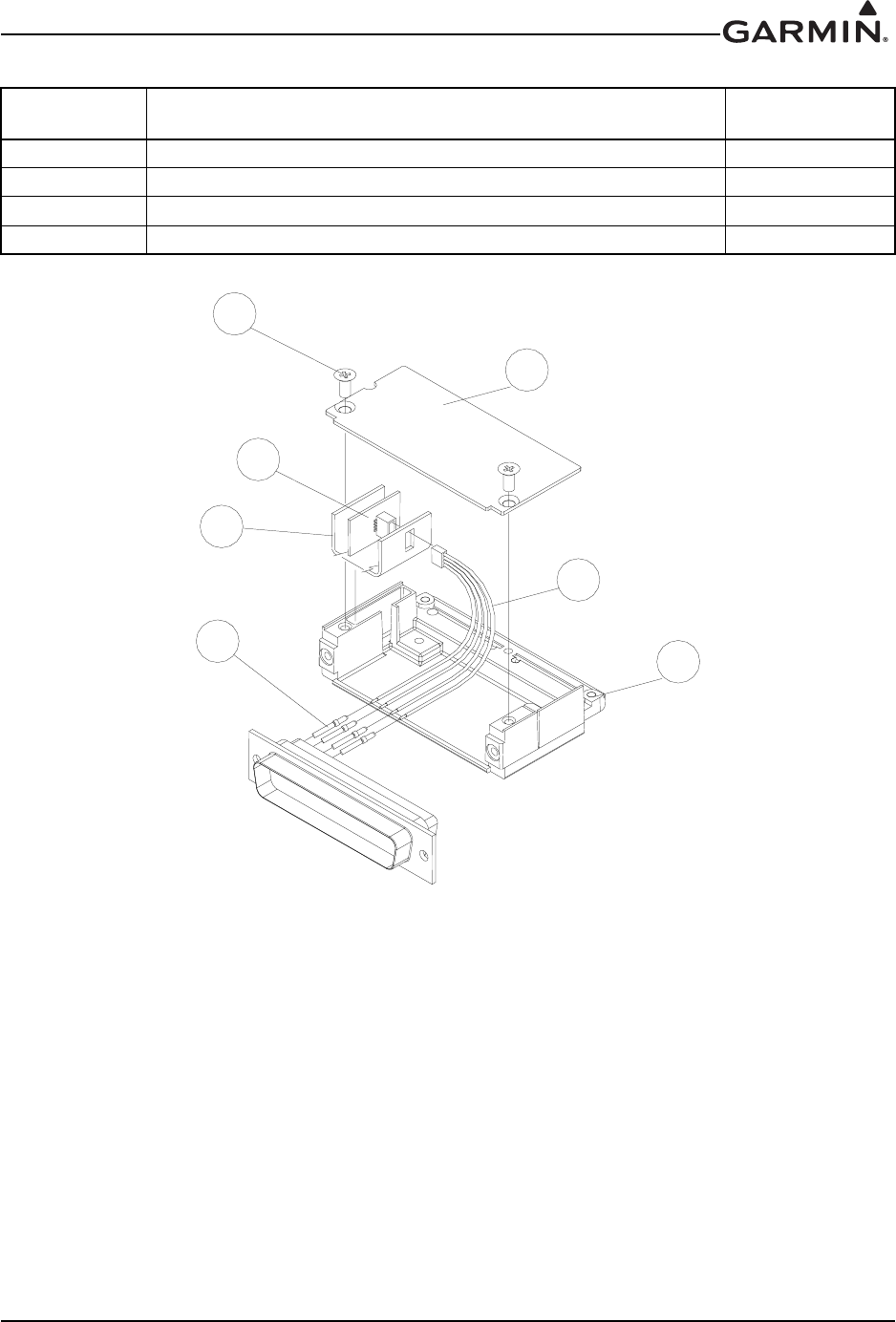
Table 6-4. Configuration Module Kit 011-00979-00 (P1001)
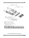
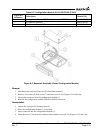
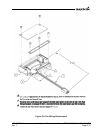
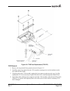
Figure 6-6. Backshell Assembly (Configuration Module with Spacer)
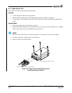
Removal
1. Disconnect the connector from the GTN.
2. Remove two screws (5) from cover (6) and remove cover.
3. Unplug the connector from the configuration module (1).
4. Remove the configuration module from the backshell connector.
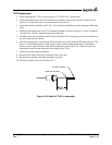
Reinstallation
1. Inspect the connector for damaged pins (4).
2. Apply spacer (2) by wrapping it around the PCB board (1) making sure to insert th
e plastic
connector mounted
on the board into the hole provided in the spacer.
3. Place the configuration module (1) in position.
4. Insert connector into the configuration module (1).
5. Place the cover (6) back on the connector and reinstall sc
rews (5).
Figure 6-6
Reference
Description Garmin P/N
1 Configuration Module, PCB Board Assembly w/EEPROM 012-00605-00
2 Spacer, Configuration Module 213-00043-00
3 4-Conductor Harness 325-00122-00
4 Pin Contact, Crimp, #22D 336-00021-00
[