


190-01007-A1 System Maintenance Manual GTN 6XX/7XX Part 23 AML STC
Rev. 7 Page 7-7
7.2.2 GMA 35 Audio Panel Checkout (GTN 7XX Only)
7.2.2.1 GMA 35 Interface Check (GTN 7XX Only)
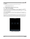
1. With the GTN running and the GMA 35 audio panel powered on, go to the Home page and to
uch
the Audio Panel key.
2. Ensure that a red “X” is not displayed over the Audio Panel key
.
After configuring the audio
panel, an in-aircraft checkout may be performed with a good microphone,
headset, speaker, and avionics receivers. For testing the marker beacon, use a ramp tester that transmits a
75 MHz marker beacon test signal.
For instructions on how to operate the GMA 35 in normal mode during checkout procedures, refer to the
GTN 725/750 GMA 35 Pilot’s Guide, P/N 190-01007-03.
NOTE
In the following procedural steps allow for variation in the configuration settings for the
particular installation under test.
7.2.2.2 Failsafe Operation Check
1. Power the GMA 35 off by pulling the audio panel circuit breaker.
2. Check the failsafe operation by exercising the COM1 microphone, microphone key and audio ov
er
the pilot’
s
headphones.
NOTE
Use of a true mono headset is required for this test to ensure proper wiring even if a stereo
jack is provided in the installation. Wiring left channel (tip contact) and right channel
(ring contact) backwards will cause failsafe mode not to function with mono headsets. Use
of a true mono headset is required for this test (not a stereo headset with a mono/stereo
switch because headset manufactures differ on how they accomplish this switching). This
will guarantee the condition of the right channel (ring terminal) being shorted to the
return (sleeve terminal) by the mono headset’s plug. During power-on operation, this
short will not damage the audio panel.
3. Verify that COM1 can key and transmit the pilot’s mic audio by verifying received side
tone or
checking re
ception of the transmission with another radio
tuned to receive this transmission (verify
Pil
ot PTT and mic operation is delivered to
this transceiver).
4.
Turn the unit back on to continue
testing.
NOTE
If the configuration setting “COM 1 is connected as COM 2” is set to True, then the
COM 2 microphone should be exercised rather than COM 1.