


190-01007-A1 System Maintenance Manual GTN 6XX/7XX Part 23 AML STC
Rev. 7 Page 3-18
HSDB Ethernet
This page displays the status of each HSDB port to be displayed. This page displays whether or not each
port is receiving data and displays whether the port is connected or not connected. The communication
status of each installed HSDB LRU is also displayed.
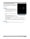
Main Indicator (Analog)
This page displays the CDI connected to the main board (P1001) to be ground checked and allows the
interface to be verified.
Analog Inputs
This page displays the bus voltage setting for Lighting Bus 1 and Lighting Bus 2 as well is the input
voltage setting for each bus. It also displays synchro heading input diagnostics information such as heading
angle, heading valid status, AC voltage, and AC frequency.
Power Stats
This page displays the number of times the GTN has powered up as well as the total elapsed operating
hours for the GTN.
WAAS Diagnostics
This page displays the WAAS engine status, including UTC date/time, current Lat/Lon, overall navigation
status, oscillator temperature, and AGC voltage. This page also allows the GPS/WAAS engine to be reset.
Temps
This page displays the current, minimum, maximum, and average board temperatures for the LED Board,
Main Board, Display Interface Board, GPS/WAAS Board, and COM Board.
Error Log
This page allows the error log to be written to the SD card in the front slot. It also allows the error log to be
cleared.
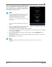
Main Data Inputs
This page allows the data on ARINC 429, RS-232, and other electrical inputs to be monitored. This is used
for checking electrical interfaces during installation and troubleshooting. Information that is not being
received by the GTN is dashed out.
VOR/ILS Indicator (Analog)
This page allows the CDI connected to the NAV board (P1004) to be ground checked and allows the NAV
indicator interface to be verified.
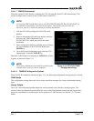
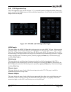
COM Board Diagnostics Page
This page displays status of the FPGA flash, nonvolatile memory, synthesizer lock calibration, and
reversionary as well as the transmitter power limit.
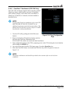
Clear Config Settings
CAUTION
This key should only be pressed if the intent is to clear all configuration settings. Touching
the Clear Config Settings key opens a confirmation window to reset all of the settings
stored in the configuration module to their defaults.