


Instruction Manual
IM-106-5500, Original Issue
August 2005
6-9
CCO 5500
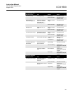
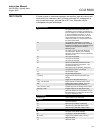
TEST POINTS If further checks on instrument operation are required, there are various test
points within the instrument. Many of these are simple DC voltages and so
may be checked using a voltmeter set to DC volts, otherwise may be
investigated using an oscilloscope:
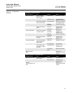
Signal processor
T1 D1 signal from receiver head with some
conditioning in the processor, smoothed by a
factor of divide by 10. Flattened saw-tooth, 32
to 45 Hz (modulation frequency) 1V pk-pk
(maximum), centred on 0V. 0V for T1 to T6
may be taken from 0V test point, top left of
board. Test-points T1 to T6 are to be found in
the center of the board.
T2 D1 signal after amplification in processor.
Flattened saw-tooth, 32 to 45 Hz, 3.5V pk-pk
(maximum), centered on 0V. Amplitude may be
varied by a trim pot. Refer to Section 4,
Detector Levels.
T3 D1 output to the A/D converter within the
micro-processor, offset by 2.5V. Flattened
saw-tooth, 32 to 45 Hz, 3.5V pk-pk (maximum),
centered on 2.5V.
T4 As T1 but for D2 signal.
T5 As T2 but for D2 signal.
T6 As T3 but for D2 signal.
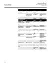
T7 Receiver ambient temperature to the A/D
converter with the micro-processor - 1mV
represents 33.8
o
F (1
o
C).
T8 Normalizing input for pressure, before A/D
converter 0.8 to 4.0V = 4 to 20 mA.
T9 As T8 except oxygen.
T10 As T8 except temperature.
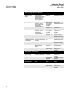
+5 and 0V Supply rails for the micro-processor. DC
voltage.
12V Supply rail for the plant status input.
+15V, -15V and 0VA Supply rails for the analog current output.
VIN Output from the D/A converter. 0 to 2.5V
represents 0 to 20 mA (4 mA at 0.V).
-15V1, 0V and +15V1 Isolated supply for the analog current output.
0VB and +12VB Isolated supply for the plant status input.
F Reference wave from the transmitter unit (via
the power supply). Square wave, 30 top 45 Hz,
5V pk-pk, centered on 2.5V.
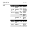
Power Supply
0V and +12V Power supply for the instrument.
Receiver
0V 0V for the receiver.
T1 Detector output without conditioning.
T2 Detector output after first stage of gain.
T3 Detector output after both stages of gain.
Transmitter
S- 0V supply to the heater cartridge.
S+ 12V supply to the heater cartridge.
M+ and M- Supply to the chopper motor (+1V DC).
T3 Reference wave.
T4 Reference wave.