Instruction Manual
IM-106-5500, Original Issue
August 2005
3-19
CCO 5500
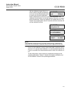
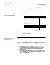
After the calibration has been conducted, a CAL FACTOR will be
calculated; this determines the calibration of the instrument. The cal
factor will be displayed for a few seconds after a calibration has been
conducted, and it can also be interrogated from Mode 4 (diagnostic
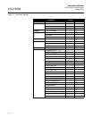
mode). Enter the cal factor into the table below, as a record of
instrument operation.
Table 3-2. Calibration Data
NOTE
Factory settings were obtained under the following conditions:
• 6.5 ft (2 m) path length
• Clean conditions
• 240V, 50 Hz supply
CURRENT OUTPUT
CALIBRATION
NOTE
This is set at the factory and should not be altered without due consideration.
The current output should now be set up using a calibrated milliammeter set
to DC current, 20 mA max. Conduct this procedure as follows :
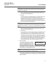
1. Connect the milliammeter to the output terminals within the signal
processor - terminals +mA and -mA.
2. Enter the SET UP MODE - CONFIGURE OUTPUT - SET ZERO
OPTION, and adjust the level using the ARROW keys until 0mA is
recorded. Record the value in brackets on the display in Table 2 -
Calibration Data.
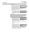
3. Enter the SETSPAN option and adjust the level using the ARROW keys
until 20 mA is recorded. Record the value in brackets on the display in
Table 2 - Calibration Data.
Calibration Data
Detector Outputs Factory Config
D2
D1
E1
E2
Calibration Data
Cal factor
Span factor
Output Calibration
Set zero
Set span


