


Instruction Manual
IM-106-5500, Original Issue
August 2005
3-5
CCO 5500
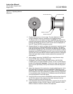
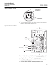
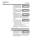
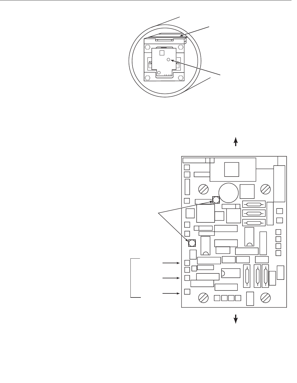
Figure 3-2. Receiver Trim Pots
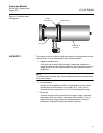
4. Trim potentiometer(s) set the gain with the receiver. Levels should be
measured with a voltmeter set to AC Volts.
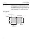
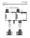
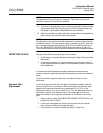
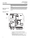
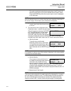
Figure 3-3. Receiver Test Points
5. Connect the voltmeter to the S0V and S1 test points, as in Figure 3-3.
Increase the gain using the trim pot at the END DETECTOR, until the
voltage is a maximum of 4V rms.
6. Repeat the above procedure for the SIDE DETECTOR, measuring
across S0V and S2 test point.
7. When the detector levels are satisfactory, replace the cover.
Control Board for
Side Detector D1
Control Board for
End Detector D2
S0V GREEN
S2 BLUE
S1 WHITE
Voltage
Indication
LEDs
TEST POINTS
End Detector
Front of Receiver