


Instruction Manual
IM-106-5500, Original Issue
August 2005
1-9
CCO 5500
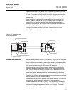
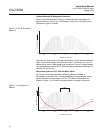
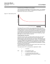
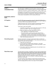
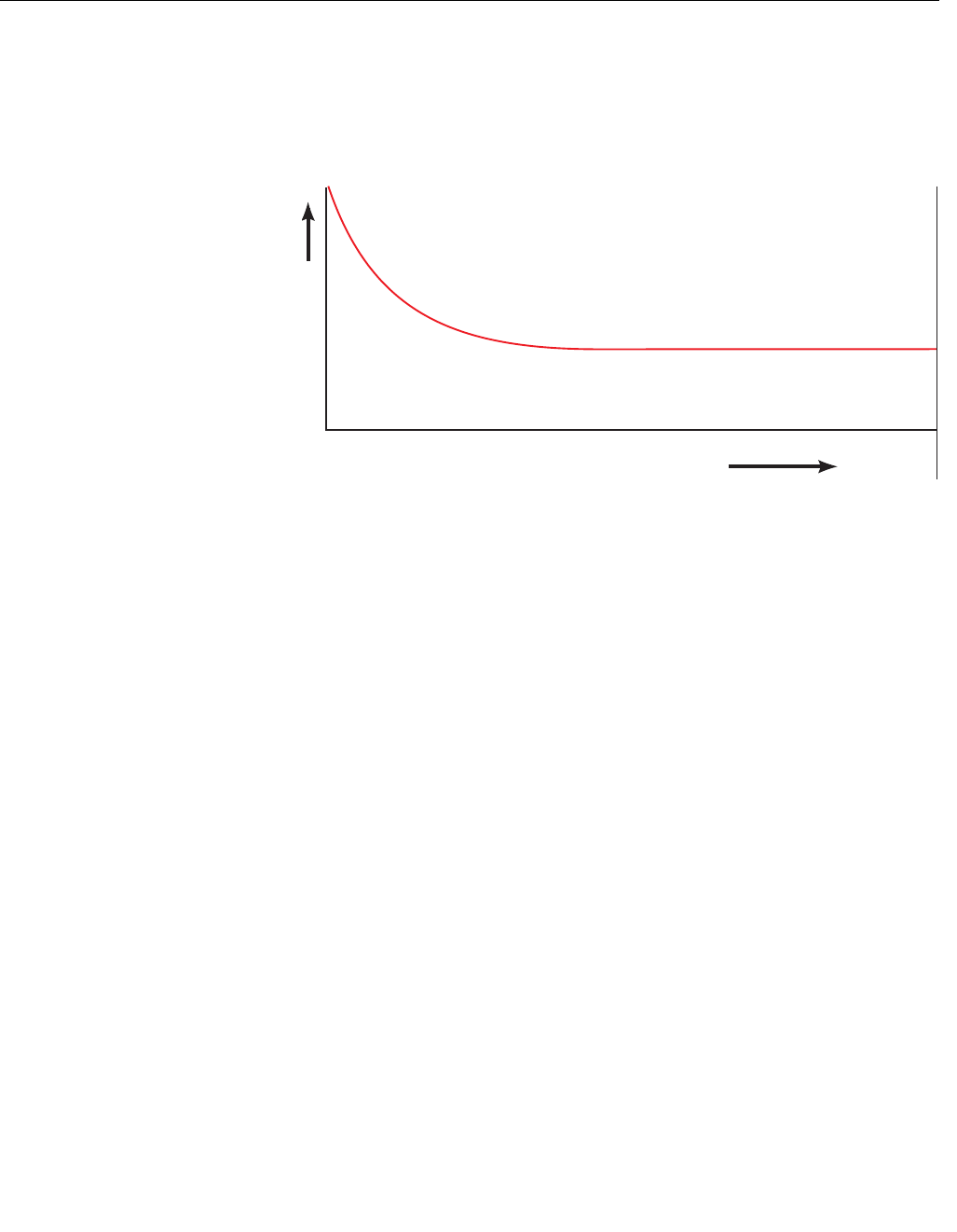
Transmissivity of CO Within the 4.7µm Band
The transmission through the gas of the IR energy at about 4.7µm is affected
by the concentration of CO. Figure 1-5 illustrates how the energy within the
selected band varies with CO concentration.
Figure 1-5. Transmissivity of CO
The shape of this curve is fixed by the characteristics of the 4.7µm filter - it
cannot change, and the curve is practically flat at CO concentrations of above
10,000 ppm.meters. A cross-duct monitor effectively measures CO molecules
in its optical path, so the same concentration of CO will have a greater effect
across a large measurement path than a small measurement path. The term
ppm.meters is the concentration of CO within the duct multiplied by the gas
path length over which it has been measured.
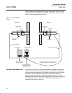
Carbon Monoxide Calculation
CCO 5500 Analyzers make two measurements of IR energy in the narrow
band around 4.7µm. Both measurements are made after the beam has
passed through the gas to be measured. One, however, also passes through
a cell containing pure CO (the gas cell shown in Figure 1-2). This absorbs all
the energy capable of being absorbed by CO and provides a reference that is
unaffected by any CO in the duct, but will be affected by any other material
(e.g. dust) which reduces the energy received from the transmitter, in exactly
the same way as the other beam.
The second beam does not have such a cell in front of it and, as such, is very
sensitive to changes in CO within the duct.
The measurement of CO is calculated from a parameter Y, where:
Y=G-K.D2/D1
and D2 = the live detector output
D1 = the reference detector output
K = a composite gain factor which takes
account of all optical and electronic gains
G = scaling factor
CO Concentration (ppm.m)
Transmission (%)
0