Instruction Manual
IM-106-5500, Original Issue
August 2005
CCO 5500
6-2
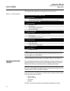
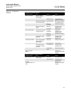
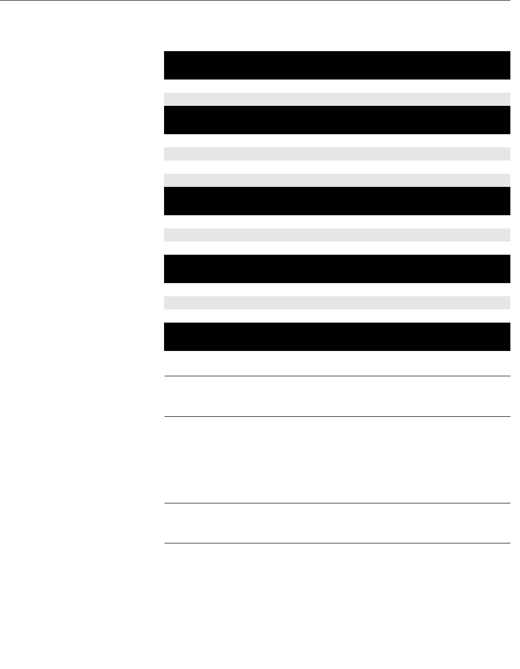
The following fault conditions are recognized by the instrument.
Table 6-1. Fault Conditions
NOTE
If a fault condition is recognized by the instrument the minutes, hours and
days averages will not be updated.
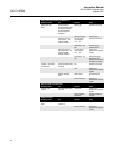
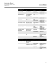
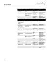
Further troubleshooting information is provided in Table 6-2 and Table 6-3.
TROUBLESHOOTING
TABLES
The troubleshooting tables provide fault diagnosis, possible causes and the
appropriate actions, if an instrument fault is suspected. Note the symptoms
and when the fault has occurred and refer to the appropriate tables.
NOTE
Be sure to use the tables from the top down and pay particular attention to the
'proceed to next TEST or CAUSE' information.
If the fault cannot be rectified by the customer then the tables should indicate
which of the four units are faulty:
• power supply
• signal processor
• transmitter
• receiver
The faulty unit can then be returned to Rosemount Analytical for repair.
Detector signals saturated (Sat# over 50)
Possible Causes
Incorrect detector gain adjustment.
Instrument condition during high opacity conditions which have now cleared.
Low detector levels (D1 < 3,000)
Possible Causes
High opacity in duct.
Dirty windows.
Incorrect detector gain adjustment.
Heater cartridge failure.
Cal factor out of range
Possible Causes
Calibration conducted during unstable duct conditions.
Poor alignment.
Incorrect detector gain adjustment.
Modulation frequency is below 30 Hz or above 45 Hz
Possible Causes
Poor supply voltage.
Faulty chopper motor.
Incorrect setting within transmitter.
Reference signal failure
Possible Causes
Chopper motor failure.


