


Instruction Manual
IM-106-5500, Original Issue
August 2005
CCO 5500
2-6
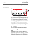
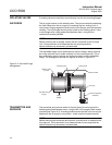
ISOLATING VALVES If isolating valves are used they mount directly onto the site mounting flanges.
AIR PURGE The air purge mounts on the isolating valve. They are mounted by separating
the front flange from the air purge by unscrewing the four locking nuts. A
'snout' and o-ring arrangement locate into the front flange; work the two apart
carefully. The front flange should now be bolted to the isolating valve if used
or site flanges with a rigid gasket fitted between them, using the four
countersunk screws provided.
NOTE
Before mounting the air purges, ensure that air is supplied to the air purge
unit. If this precaution is not observed then the air purge and the
optical surfaces may be severely contaminated.
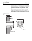
The adjustable flange is then positioned on the front flange, taking care that
the o-ring seal and 'snout' locate smoothly into the central aperture. This is
then secured by the four locking nuts that screw down onto the adjustable
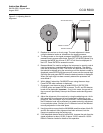
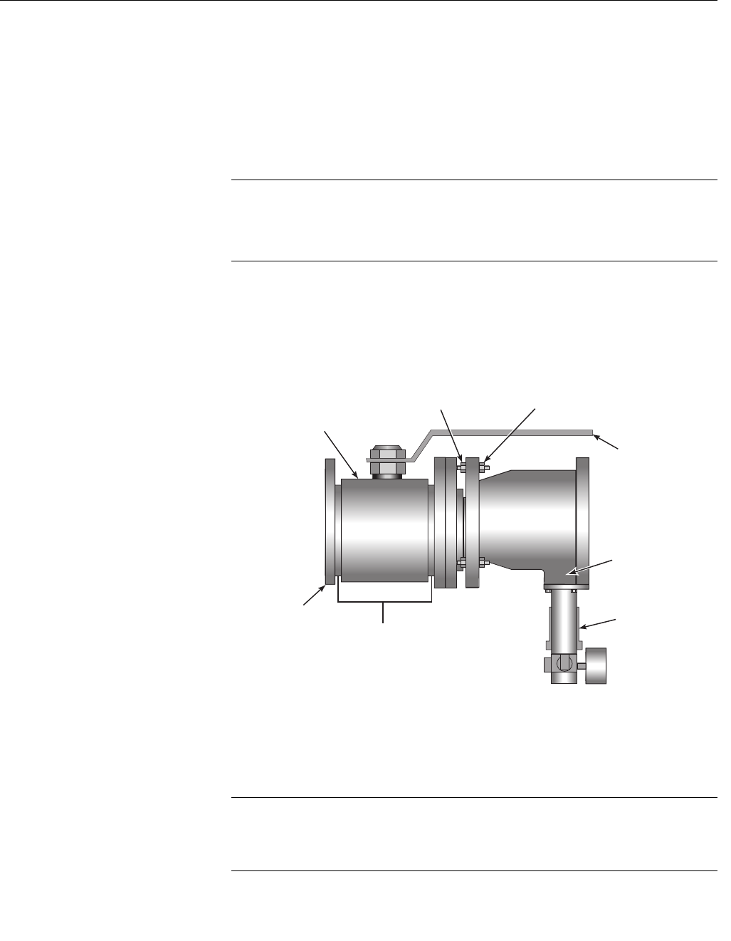
flange. The arrangement should now appear as shown in Figure 2-2.
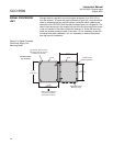
Figure 2-2. Valve and Purge
Arrangement
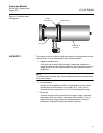
TRANSMITTER AND
RECEIVER
The transmitter and receiver attach to the rear face of the air purge with a
flexible gasket fitted between them, using the M6 x 20 hexagon head screws
provided (see Figure 2-3). A locating dowel ensures that the units can only be
attached to the air purge in one position - make sure this locates correctly.
NOTE
Before mounting the transmitter and receiver, ensure that air is supplied to the
air purge unit. If this precaution is not observed then the air purge and the
optical surfaces may be severely contaminated.
Locking Nuts
Valve Handle
Air Purge
Pressure Regulator
Assembly
Adjusting Nuts
Rigid
Gasket
Site Mounting
Flange
Isolation Valve
(if used)