


Instruction Manual
IM-106-5500, Original Issue
August 2005
CCO 5500
5-2
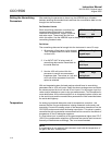
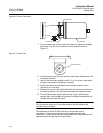
To replace an element proceed as follows:
1. Switch OFF power.
2. Remove the rear cover plate from the transmitter by removing the four
retaining screws. Note that these screws are not captive.
3. Carefully remove the PCB now revealed by unscrewing the three
retaining screws.
4. Disconnect the two wires from the terminals at the rear of the heater
assembly by removing the two M3 nuts.
5. Remove the heater assembly by unscrewing the three screws. These
are captive screws and cannot be removed completely. The heater
assembly may then be withdrawn from the transmitter and discarded.
6. Refit a replacement unit by reversing the above procedure.
7. After completion, switch ON the power and allow fifteen minutes for the
heater to attain temperature after which the equipment will start to
calculate the gas levels.
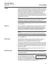
Replacement of Chopper
Motor Assembly
1. Turn the power OFF and remove the transmitter from its air purge.
2. Remove the four screws holding the transmitter front flange in position
and remove the front flange.
3. Turn the three brass extended head screws counterclockwise (unscrew)
to loosen assembly.
4. Carefully lift out the assembly and remove the center plate from the
transmitter body.
5. De-solder the red and black wires attached to the chopper motor.
6. Remove the three screws holding the chopper motor to the center plate.
7. Replace the chopper motor and reverse the above procedure.
8. Turn the power ON and check the chopper motor frequency by viewing
in Mode 4 - Diagnostics. Adjust using the trim potentiometer as
described in “Transmitter Adjustments” on page 3-7.
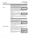
Replacement of Gas
Cells
Transmitter
1. Turn the power OFF and remove the transmitter from its air purge.
2. Remove the four screws holding the transmitter front flange in position
and remove the front flange.
3. Turn the three brass extended head screws counterclockwise (unscrew)
to loosen assembly.
4. Carefully lift out the assembly and ease the PCB off its supports.
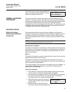
5. Unscrew the M3 x 6 slotted screw (or grub screw on some models) at
the end of the gas cell assembly.
6. Pry the gas cell off the stepper motor shaft.
7. Place the new gas cell in position and reverse the above process.
8. Turn ON the power and recalibrate. Refer to Section 4, Calibrate.