


Instruction Manual
IM-106-5500, Original Issue
August 2005
CCO 5500
2-2
SAFETY
CONSIDERATIONS
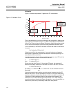
The mains power is supplied to the whole system via the power supply.
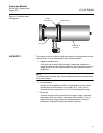
During installation, DO NOT connect the system to the mains until all units are
in place and fully wired up. Keep the isolating valves, if used, CLOSED. The
compressed air (to be supplied to the air purges) must be turned OFF until the
full installation is complete. If any servicing or rewiring is to be performed
ensure that the power supply is isolated. For configuration the system needs
to have power, compressed air and the isolating valves open.
ELECTRICAL SUPPLY
DATA
AC Supplies
The CCO 5500 may be powered from either 85-132V AC/170-264V AC at
47-440 Hz. A switch within the power supply unit selects the input voltage and
an internal 2A/20 mm fuse protects the instrument.
Voltage fluctuations within the above ranges are tolerated without loss of
performance and the total power requirement is less than 50VA.
Outputs Three forms of output are provided:
1. A selectable, fully isolated, current output (either 4-20 mA or 0-20 mA),
maximum load 500S - taken from the signal processor.
2. Single pole change-over relays (rating 250V at 10A), for:
• Alarm triggering at a selectable gas threshold
• Data valid indication, operating under power failure and any
equipment fault condition - see the basic fault finding section for
further details - contact outputs are taken from the power supply unit
3. 4-wire serial data link for 2-way communication with a central processor
- taken from the signal processor unit.
Normalizing Inputs Pressure, temperature, and oxygen values can be held to normalize the
calculated gas value to standard conditions. These values may be read by the
instrument using the following methods:
1. Fixed value from the key pad.
2. 4-20 mA outputs from measurement transducers - the ranges
represented by these inputs are set from within the processor - inputs
are taken to the signal processor.
3. If the analyzer is part of an integrated system, the serial data line can
carry the normalizing values.
Plant Status Input The plant status input facility is available to prevent the rolling average stacks
being diluted by measurements made during periods where the plant is shut
down. It is governed by one of three choices; a serial input (from an integrated
system), the logic input (terminals PS1 and PS2 in the signal processor) and
multiple. Multiple has five options; temperature, oxygen, water vapor
thresholds, and logic input. It is set in Mode 5. All these are described in more
detail later in this manual.
In normal operation (plant operating), the plant status will register as ON.
However, if the plant status condition is broken, the status will change to OFF
and the averaging stacks (minutes, hours, days) will not be updated.