


Instruction Manual
IM-106-5500, Original Issue
August 2005
CCO 5500
2-8
SIGNAL PROCESSOR
UNIT
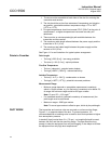
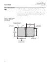
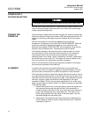
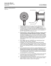
Enough cable is supplied to mount the signal processor up to 33 ft (10 m)
from the receiver. To mount the signal processor (Figure 2-4), first remove the
cover by loosening the four captive screws, unplug the ribbon cable at the
connector on the lid PCB. Note that the processor case has a hinged lid. The
case is then secured to a firm support by use of the four mounting holes found
in the four corners of the case, outside the sealing rim. Since the mounting
holes are located outside the seal of the case, it is not necessary to seal the
mounting holes after installation, nor is it necessary to remove the circuitry
from the case for installation.
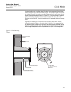
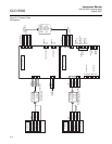
Figure 2-4. Signal Processor
Unit/Power Supply Unit
Mounting Detail
9.1 in.
(230 mm)
7.9 in.
(200 mm)
Approx. 6 in. (150 mm)
free space required
below box for cables
Cover Seal - Note that the
mounting holes are beyond
the extent of the seal
Cover
Assembled Box
110 mm Deep
Base
7.1 in.
(180 mm)
4 Holes for M6
Mounting Screws
7.1 in.
(180 mm)
Cable Gland Entry
Blanking Plugs