Instruction Manual
IM-106-5500, Original Issue
August 2005
CCO 5500
1-2
Each of these units is designed to be rugged and durable. They are all fully
sealed to IP65 standards and are suitable for outside mounting, without the
need for further weatherproof enclosures.
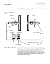
Figure 1-1. Typical System
Layout
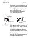
Infrared Transmitter Unit At the heart of this unit is a small heater assembly designed to give a high
intensity uniform source of infrared energy over a long lifetime, in excess of
two years continuous operation, with a power consumption of only 26 watts.
The heater has a stainless steel cylindrical core, plasma coated with
refractory, and around which is a 'Kanthal' heating element. This is then
enclosed within refractory fibers and encapsulated in an aluminium cartridge.
In the infrequent event of failure, the complete heater assembly can be
replaced on site within ten minutes.
Transmitter
Isolation Valve
(If Used)
Pressure
Regulator
Power Supply
Signal Processor
33 ft(10 m) Max.
Mains Supply &
Contact Outputs
Analogue Outputs,
Normalizing Inputs &
Se
ri
a
lD
a
t
a
P
o
rt
82 ft(25 m) Maximum Total Cable Length
Between Receiver & Power Supply
33 ft(10 m) Standard
Purge Air
Receiver
Site Mounting
Flange
Air Purge


