


Instruction Manual
IM-106-5500, Original Issue
August 2005
2-5
CCO 5500
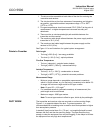
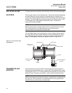
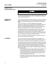
A hole should be cut on either side of the duct to be measured; these holes
should accept a 'slip fit' with the stand-off pipe. The stand-off pipe should now
be welded into each hole and a mounting flange welded to each pipe with the
tapped holes positioned as shown in Figure 2-1 (it may be easier to weld the
pipe and the flange together before they are fixed to the duct). To avoid
vibration and movement, it may be necessary to fit spreader plates or bracing
fillets.
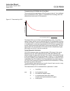
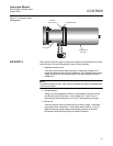
Alignment is satisfactory if one orifice can be clearly seen when viewed
through the stand-off pipe on the other side of the duct. It is suggested that
the stand-off pipe is 'tacked' on to the duct and the alignment checked visually
before a complete weld is made. The alignment of these holes is not critical,
as the integral adjustable mount compensates for up to 4
o
of misalignment.
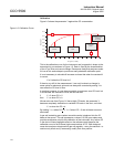
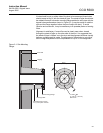
Figure 2-1. Site Mounting
Flange
Duct Wall
Lagging
6.5 in.
(165 mm)
Site Mounting Flange
Stand-Off Pipe (if used)
3 in.(75 mm) dia. nominal
Bracing Fillets
4 Holes M8
on 4.92 in. (125 mm)
Bolt Circle