


Instruction Manual
IM-106-5500, Original Issue
August 2005
2-3
CCO 5500
NOTE
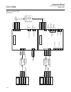
For normal operation terminals PS1 and PS2 must not be linked together.
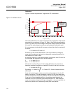
CABLE REQUIREMENTS 1. Power supply to signal processor - 7-core, shielded, multi-stranded,
6/0.2 mm. 0.5 mm
2
.
NOTE
Although screened cable is specified for the interconnecting cable, it is not
necessary for the cable to be grounded.
2. Current loop output - any suitable 2-conductor cable - maximum length
depends on keeping output load within the 500S maximum load
requirement.
3. Contact outputs - any 2-conductor cable capable of supplying the power
to the warning device/relay etc. 250V, 10A maximum.
4. A.C. power - any suitable 3-conductor power cable capable of
transmitting 50VA.
5. Serial data link (if required) - twin twisted pair shielded cable - see IEM
Communications Manual for further details (Doc. ID 0006/6).
6. Analog inputs - any suitable 2-conductor cable - Rosemount
instruments have an internal impedance of 240S for these inputs.
UNPACKING THE
EQUIPMENT
A typical Rosemount Analytical CCO 5500 Carbon Monoxide (CO) Analyzer
should contain the following items. Record the part number, serial number,
and order number for each component of your system.
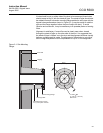
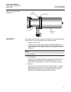
1. Transmitter with 33 ft (10 m) of cable and air purge.
2. Receiver with 33 ft (10 m) of cable and air purge.
3. Signal processor.
4. Power supply.
5. Site mounting flange (2).
6. Gaskets (4), selected screws and washers.
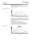
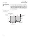
SELECTING LOCATION The equipment is designed for mounting on boiler ducting or stacks in
positions open to the weather. It is fully sealed and requires no further
enclosures or protection. The specific location of the instrument will depend
on the application and user requirements, but the following considerations
should be made when choosing a site.