


Instruction Manual
IM-106-5500, Original Issue
August 2005
CCO 5500
3-4
NOTE
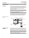
The alignment of the receiver unit is important. Take time to ensure that
maximum values of D1 and D2 are obtained.
11. To 'fine tune' the alignment, return once more and adjust the transmitter
flange, again observing the values of D1 and D2 as appropriate; lock
the flange in place when a MAXIMUM has been obtained.
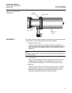
12. After this procedure has been followed, the alignment is completed and
there is rarely any need for further adjustments.
NOTE
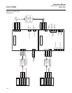
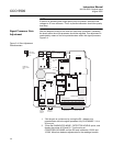
The alignment of the receiver may be conducted by monitoring the output of
the detector directly. This can be done using a voltmeter set to AC volts (10V
max.) measuring across test points S0V and S2 for D3 and S0V and S1 for
D1 on the RECEIVER CONTROL BOARD within the receiver (Figure 3-3).
This is useful should the receiver be some distance from the signal processor.
DETECTOR LEVELS The gain of the detector signals is set in two locations:
1. In the receiver: two potentiometers set the gain. Refer to Receiver Gain
Adjustment.
2. In the signal processor: trim potentiometers adjust the level of the D1
and D2 signals before they enter the microprocessor. Refer to Receiver
Gain Adjustment.
It is essential that the alignment procedure has been conducted and a
maximum detector signal obtained before attempting to optimize the detector
levels.
To give an optimum signal-to-noise ratio, the detector levels must be
maximized.
Receiver Gain
Adjustment
For the best signal-to-noise ratio, the gain of the detector signals within the
receiver must be set to a maximum, without saturating. The gains will have
been set by Rosemount Analytical at a pathlength of 6.5 ft (2 m). If the
pathlength is above 13 ft (4 m) or below 5 ft (1.5 m), this adjustment may be
necessary to optimize the detector levels. If the pathlength is within this
range, this section may be ignored unless there is insufficient or too much
gain.
1. Enter the Setup mode, CALIBRATE OPTION-SET DETECTORS, and
display the value of D2/D1.
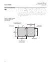
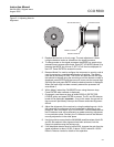
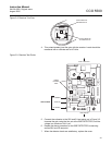
2. Loosen the cable gland and remove the end cap from the receiver
body, letting the cable slip through the gland.
3. The receiver can now be accessed as shown in Figure 3-2.