


Instruction Manual
IM-106-5500, Original Issue
August 2005
CCO 5500
3-6
NOTE
If the duct is operating and a high opacity may be present, reduce the set
voltages to 2V rms maximum. This is to prevent saturation should the opacity
level drop.
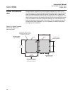
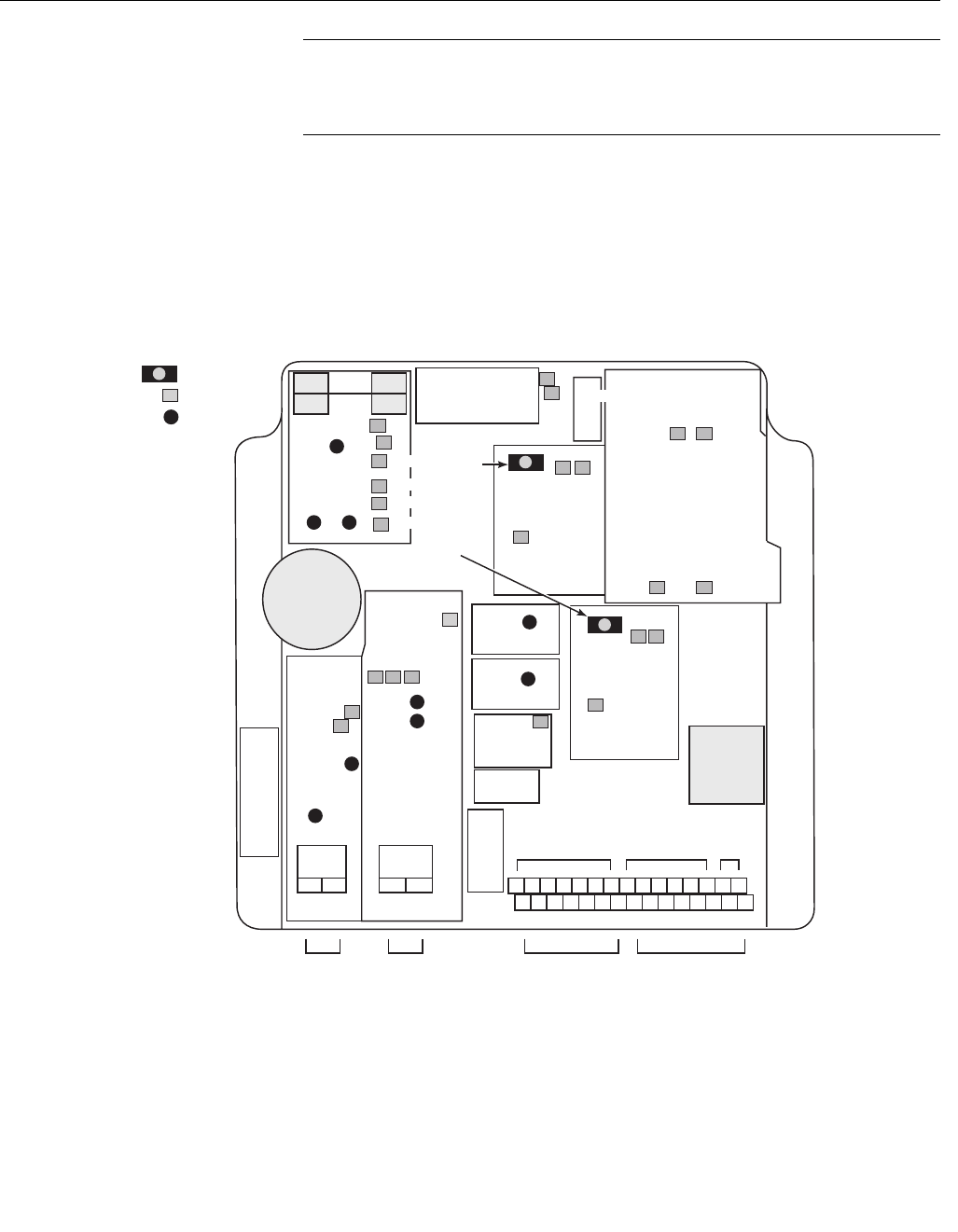
Signal Processor Gain
Adjustment
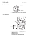
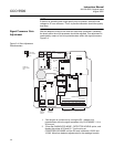
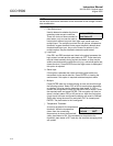
After the detector level(s) at the receiver have been optimized if necessary,
the levels within the micro-processor should be adjusted. This adjustment is
conducted by means of two trim potentiometers within the signal processor,
Figure 3-4.
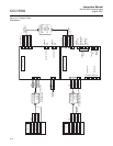
Figure 3-4. Gain Adjustment
Potentiometers
1. *Set the gain to a minimum by turning the D2 - detector trim
potentiometer within the signal processor fully CLOCKWISE - it is a
20-turn pot.
2. *Enter the DIAGNOSTIC MODE - DETECTOR LEVELS option, and
display the values of D2 and D1. Turn the trim pot
COUNTERCLOCKWISE until the D2 level is between 12,000 and
15,000. Allow time between adjustments for the readings to settle.
-15
+15
+5
0V
5V
12V
+15V
0VA
-15V
REG
CON3
COUNT 1P
COUNT 3
COM4
T7
T10
T8
T9
T2
T3
T5
T6
D2 TRIM
POT
T4
T1
M-DIR
D1 TRIM
POT
SOL MDRV
F
VIN
0V1
-15V1
+15V1
+V1
-V1
0VB
+12VB
PS1
PS2
PS
+12V
2A
SB
FUSE
1 2 3 4 5 6 7 8 9 10 11 12 13 14 15
16 17 18 19 20 21 22 23 24 25 26 27 28 29 30
POWER SUPPLY NOT USED
NORMALIZING IPs
PLANT
STATUS
INPUT
ANALOG
OUTPUT
RECEIVER SERIAL DATA
TRIM POT
TEST POINT
LED
TRIM POT.
TEST POINT
LED
+mA 0mA