Instruction Manual
IM-106-5500, Original Issue
August 2005
CCO 5500
6-8
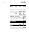
COMPONENT TESTS Some instrument components/operation can be verified as follows:
Heater Cartridge Perform the steps for Section 5, Replacement of the Heater Element within
the transmitter up to step 4. Remove one lead from the heater cartridge and
measure the resistance across the two cartridge terminals. It should be about
3.5S. If the circuit is open the heater cartridge needs replacing.
Chopper Motor 1. Turn the power ON.
2. Observe the chopper motor and blade between the lens and heater
cartridge. If the blade is spinning, the chopper motor is OK.
3. If the blade is not spinning, the supply to the chopper motor can be
measured at the test points M+ and M– on the board to the front of the
unit (nearest the lens) - it should be about 1V DC. If it is, the chopper
motor assembly requires changing; if it is, not the transmitter unit is
faulty.
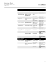
LED INDICATIONS If instrument malfunction is suspected, there are LEDs within the instrument
indicating various power rails and equipment operations.
Signal Processor LEDs
5V, -15, +15 Situated top/left of processor. Should all be
ON, indicating that the power supplies to the
instrument are functioning correctly.
M-DIR Should operate approximately every 4
seconds.
SOL_MDRV Supply to the solenoid that drives the filter into
the optical path within the receiver pulses
every time the M-DIR changes (approximately
every 2 seconds).
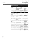
+V1, -V1 and +12V Middle bottom left of board. All should be ON.
Power supplies to the isolated analog current
output.
+12V Bottom left of board. Should be ON. Indication
of the isolated supply for the plant status input.
PS Bottom left of board. In normal operation, this
LED should be OFF. During plant-off periods,
however, if the plant status input is being used,
this LED will illuminate and the rolling averages
not updated.
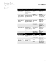
Receiver LEDs
+V and -V These LEDs should be ON indicating that the
power supplies within the unit are functioning
correctly.
Transmitter LEDs
+V and -V These LEDs should be ON indicating that the
power supplies within the unit are functioning
correctly.
Power Supply LED
+12V This LED should be ON indicating that the
power supply unit is functioning correctly. This
LED will extinguish should the supply voltage
drop from 12 to 11V.


